.................................. Return to Sumner's Home Page....
Return to N Scale RR Main Menu........ Return to Decoder Install Menu
=========================================
...............Previous Page.............................Next Page If There Is One
=========================================
--- ESU Decoder in Bachmann N Scale Doodlebug – Pt. 2 ---
============================================
Part 2 ….........................
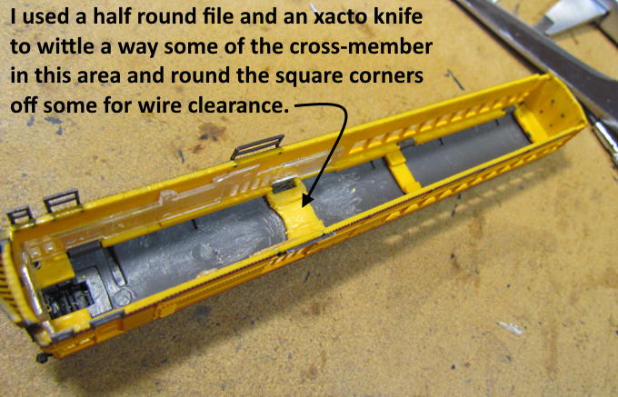
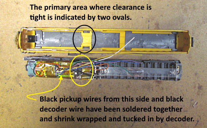
The one area where clearance is tight is right above the motor contacts area where there is also a cross-member in the shell.
I filed it the best I could and whittled away at the area with an Xacto knife to make it a little easier for the wiring to pass that point.
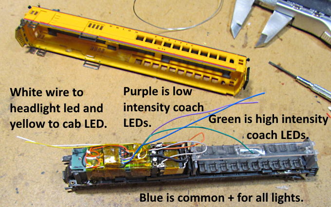
The blue above is the common positive that needs to go to all the LEDs and the other colored wires from the decoder also go to the LEDs and the decoder will turn the circuits on and off.
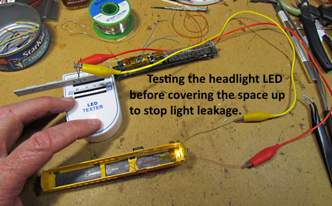
If I can I like to test the LEDs before connecting them to the decoder wires.
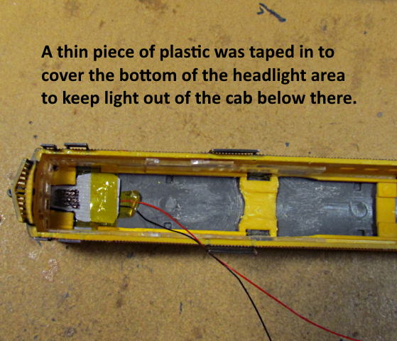
When 3D printing at times the print is started with what is called a 'raft'. It is a very think 3D printed platform that the rest of the print attaches to. The reason for it is that some prints don't have much initial surface area so don't stick well to the build table on the printer. The raft does and the part sticks well to the raft in most cases. When the print is done you separate the print for the raft and usually throw the raft away. I keep some and in this case cut a section out of a raft and used it to cover the area under the headlight to stop light bleed from it down into the cab area of the loco. In the picture above the headlight LED is on the other side of that piece of raft. You could use any number of things to accomplish the same end result.
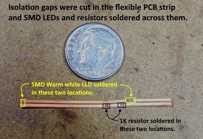
Next I tackled the two LEDs for the passenger area. I wanted 2 LEDs to make it look a little more like it would we lighting going along above that area. One could make it even more LEDs if they desired and picked the resistors out that would work for how many LEDs they were using.
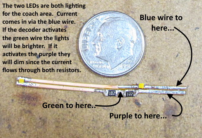
I wanted to have two intensities for the lights (LEDs). I did this by having two resistors in the circuit. One of the decoder wires attaches between the two resistors and the other attaches past both of them to the flexible PCB strip. If the decoder activates (grounds) the wire that connects between the resistors the LEDs are brighter since the current flows through only one resistor. If that wire is turned off and the other wire is turned on by the decoder the current then flows through both resistors and the lights dim. I look at the dim mode being there for later in the evening when the lights are dimmed so that passengers can possibly sleep.
More on how to use the strips and where to find them ( HERE ).
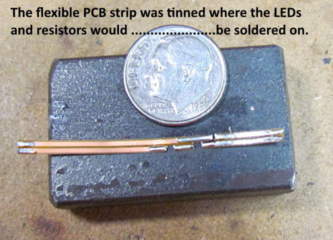
After the isolation cuts have been put in the strip where the LEDs or resistors will go the strip is tinned adjacent to the cuts and at the end where a LED will bridge the two contact strips.
I really find these strips useful and even though I haven't found a U.S. Source for them they are well worth the effort of having them shipped to the U.S.. For less than $30 I probably have a lifetime supply for decoder install and other projects such as my Turntable Project ( HERE ).
The PCB strip above takes care of the passenger area LEDs and wiring but I still needed to take care of ….
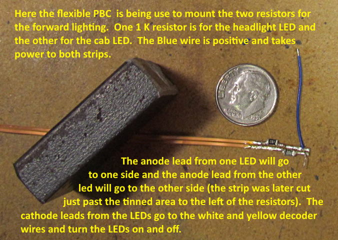
…. the LEDs in the cab and headlight. Above I'm making that strip. The blue power wire spans both contact strips and there is a cut in both contact strip with a resistor soldered in above it. After the picture was taken the flexible PCB was cut right above the word 'LED' in the first sentence. The red anode wire to the headlight LED was soldered to one side just past one resistor and the red anode to the cab LED was soldered to the other side.
The black LED wire from the headlight LED was soldered to the white decoder wire and the black LED wire from the cab LED was soldered to the yellow decoder wire.
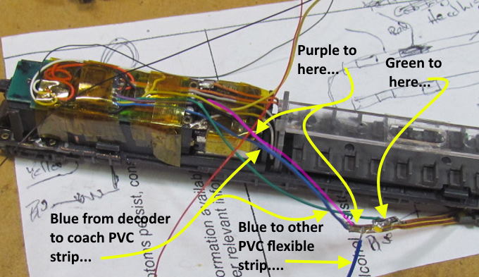
Above we see the wiring to the PCB strip that has the passenger LEDs on it. Also at the bottom a second blue wire has been soldered near the common positive blue decoder wire to take the current to the second PCB strip that has the resistors for the headlight and cab LEDs on it.
…....................... continued on the next page …........................................
=========================================
...........................On..............e.........Next Page If There Is One