.................................. Return to Sumner's Home Page....
Return to N Scale RR Main Menu........ Return to Decoder Install Menu
=========================================
...............Previous Page.............................Next Page If There Is One
=========================================
--- ESU Decoder in Bachmann N Scale Doodlebug – Pt. 1 ---
============================================
I'm trying to model roughly UP in the late 40's to early 70's but once I saw a UP painted Doodlebug I was bitten. Not sure if any were still active in my time period but I'll make it work in my make-believe world.
On researching them I found out that they were produced by Bachmann during the infamous 'white gear' years. These gears are noted for breaking and a number of the ones I found on eBay would say something like 'runs but makes a noise'. I sent a message to the seller of the UP Doodlebug I found and asked about how it ran and if there were any obvious noises. The report came back 'no' so I bought it.
Upon arrival I was a little disappointed in how it ran. Mark ( Spookshow ) actually said that for the time period it was build in that it was a good runner. I struggled to get the shell off but finally succeeded and messed with the motor contacts a little and she started running pretty darn good. Next problem was it struggled to get through my hand-laid turnouts on my small test tracks that has small radius's. It is very light at the passenger end and that was the end that was having problems. With the shell off I added weight but that didn't fix the problem. I then checked the wheel gauge and it was off on all four truck just a bit. I messed with that and it seems to of fixed the problem 95% of the time now. I still have a couple turnouts that it will derail in some times. Other locos don't derail in them so the verdict is out.
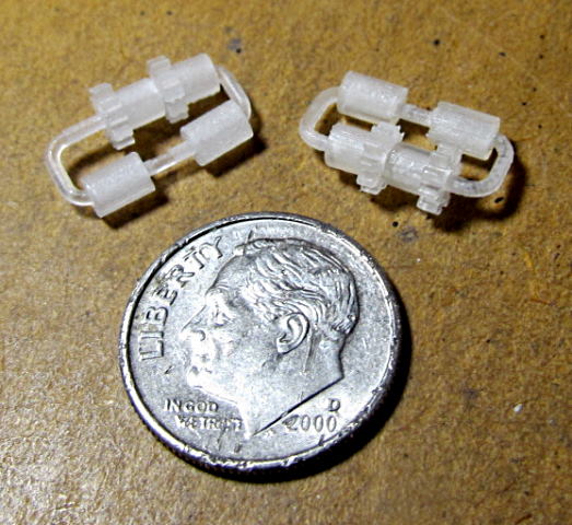
A number of the Doodlebugs don't run well due to broken gears in the trucks. They are the 'infamous white gears' that Bachmann used for a while. There now is a fairly inexpensive fix for that.
James of James Trains now produces them (see above). I bought the ones shown above to have on hand. It seems the three Doodlebugs I have maybe don't have broken gears at this point but while they are available I got them. Next time I take the shell off I'll take a closer look and I still have one of those to convert to DCC. More info from James about the Doodlebug and the gear problem ( HERE ) and ( HERE ) and how to order them on Shapeways ( HERE ).
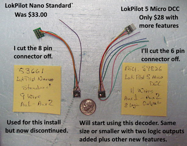
With all of that being said I've fallen in love with watching it circle the test track and run in and out of the spurs I have. I can run DC or DCC on the test track with the flip of a switch but I'm changing all the used older engines I'm buying to DCC thus that now needed to be addressed. At first I thought I was going to have to probably use some of the passenger area for the decoder. I've used a number of $16 to $24 Digitrax (DZ123 & DZ126T) decoders in my installs but I had bought a couple LokPilot Nano Standards last year to also try out.
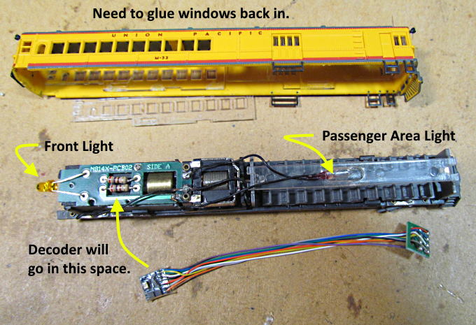
The Nano Standard is smaller and thinner that the Digitrax decoders I'd been using and it looked like I might be able to put it at the top of the frame in the 'baggage' area. The Nano Standard is also a 4 function decoder and I thought I might be able to add some lighting effects with the additional functions, which I hadn't done to this point in my decoder installs. I'd only been using the forward and rear lights. The Doodlebug didn't have a rear light. It had a front light and passenger area light. My plan was to have the headlight, a light in the cab, two lights in the passenger area that could be either bright or dimmed for late night running.
On another note, after liking the Nano Standard I decided to get a couple more for future installs. I found out that although a few distributors have them they have been discontinued (at least what I was told). I ordered instead a couple of the newer LokPilot 5 Micro DCC decoders as shown above. I think I'm going to like these even more. Besides the 2 Aux outputs they also have 2 additional logic outputs. SBS sells a very small converter circuit that you can use to convert the logic outputs into outputs that can power about any LED or probably something else. You can build your own circuit but I thought the $8 for one of Bryan's circuits was more than fair. The newer decoder also has other features not available in the Nano Standard and it is also cheaper, not much more than I was spending on a DZ127. I'll still use some of the Digitrax decoders in locos that I don't plan on running much but want them to be DCC but I'm seeing why ESU decoders are so popular even though you will have to spend a bit more.
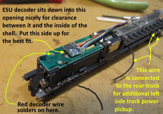
Moving on, the plan was to remove the front light, passenger light and the resistors on the PCB and place the decoder where the resistors were since it could sit down into that recess enough that the shell could go back on.
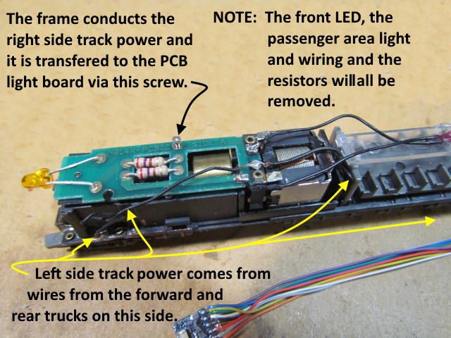
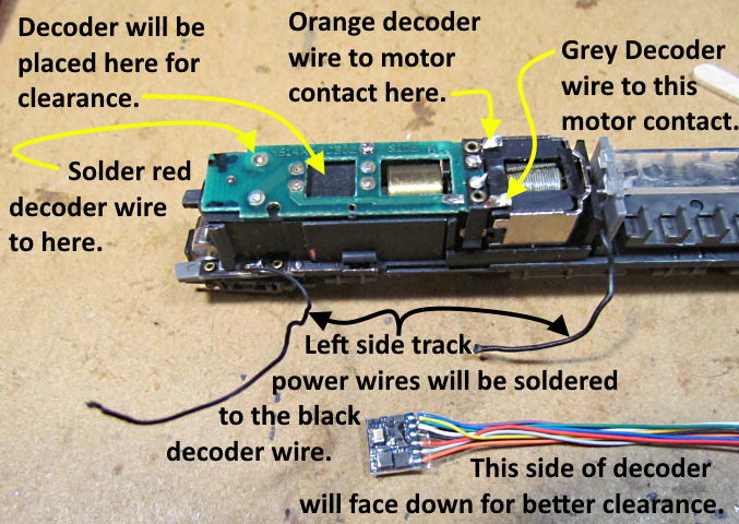
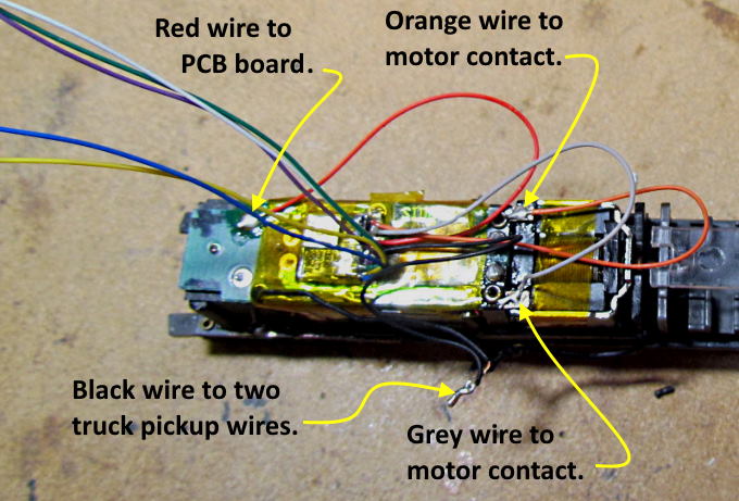
It took a bit to figure out how the track power was getting to the PCB board. Left side power (side shown above) comes from the front and rear wheels/trucks on this side. You can see where the pickups are isolated from the frame (bottom left yellow arrow) at the front and rear of the chassis. Power from the two points goes up to the motor contacts (DC) through the two black wires that are pointed out.
Right side track power is picked up by the wheels/trucks on that side and transferred to the entire frame. When the screw is tightened on the top of the PCB board in the middle far side the power from the frame goes to the pad and a trace on that side of the PCB board.
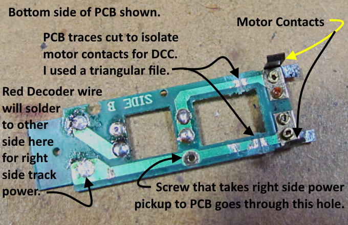
Since the PCB also has the motor contacts on it I decided to keep it and use it for wiring the power input to the decoder and the power from the decoder to the motor. This was simple and proved to work really well. I cut the two traces by the motor contacts. That isolated them.
Above you see the side of the decoder that has a couple components that stick up more than the ones on the other side. This side will be placed 'down' in the square hole in the PCB resulting in more clearance shell clearance above the decoder. The black input decoder wire will connect to the two track pickup wires at the bottom and the red input decoder wire will be soldered to the pad at the back of the PCB. The orange and grey decoder wires will go to the solder pads on the motor contacts.
Except for doing the additional lighting wiring I want to do this is really and easy decoder install using the small ESU decoder. There is no frame milling. I clearance the inside of the shell a bit and might not needed to of done that. The use of the old light board gives one easy places to solder the decoder wires to for track pickup and motor output.
.
.
.
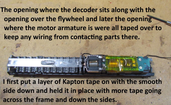
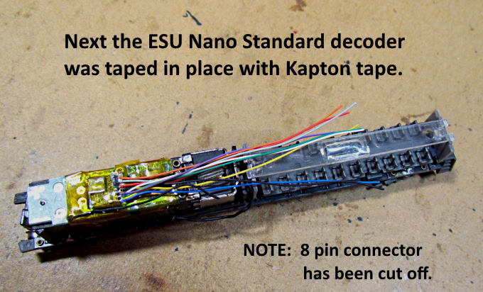
After the picture above was taken I cut the black wires where they had been soldered together shorter than shown and put a short piece of shrink wrap on the solder joint. Then tucked them in under the wires coming out of the decoder. All the other solder connects shown above were to available solder pads.
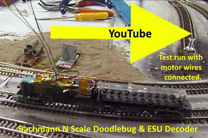
Before moving on to the lighting I put the loco on the test track and ran it to make sure the motor wiring and decoder was working. You can see the video ( HERE ) or by clicking on the image above.
…....................... continued on the next page …........................................
=========================================
...........................On..............e.........Next Page If There Is One