.................................. Return to Sumner's Home Page....
Return to N Scale RR Main Menu........ Return to DCC++ Menu
=========================================
..............Previous Page.............................. Return to WiTcontroller Menu
=========================================
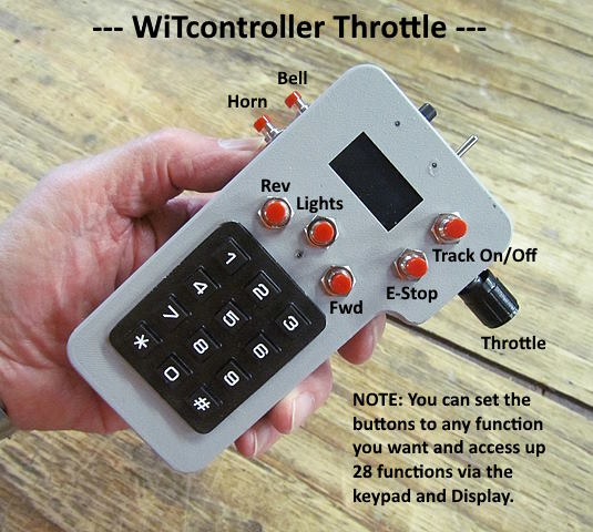
…...................................--- WiTcontroller Throttle ---
.................... --- GPIO Inputs Part 4 ---
============================================
.
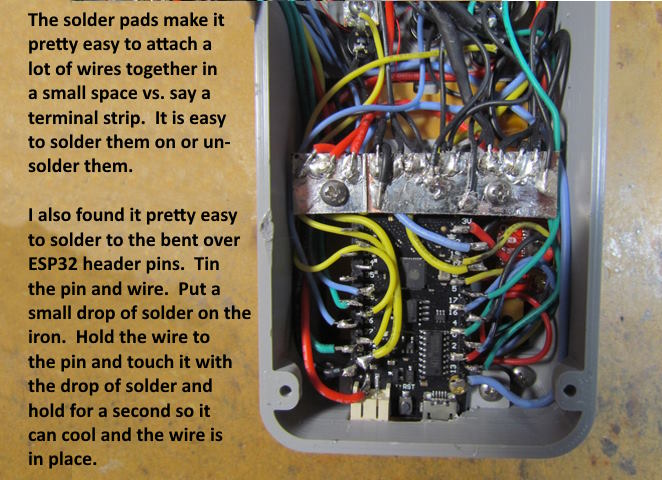
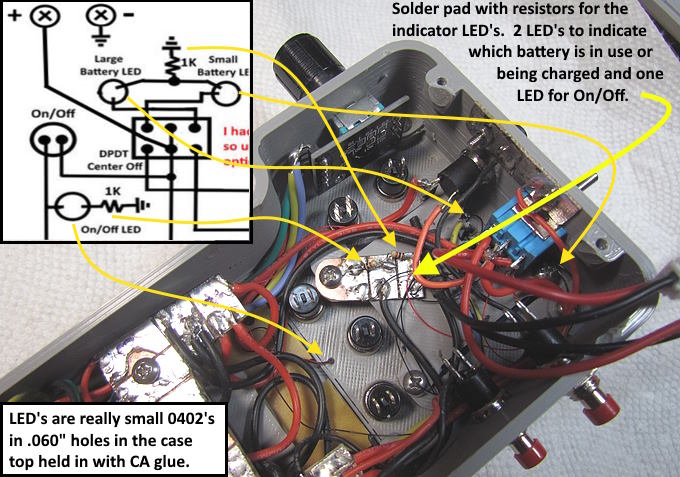
I made another little solder pad for the LED circuits. A negative lead goes to the center and there is a 1K resistor from the center to each outer pad. The battery LED negative wires both go to one side and the On/Off LED wire goes tot the other side. You can have two on one side as only one is on at a time. Vary the resistance values if you want the LEDs at a different intensity.
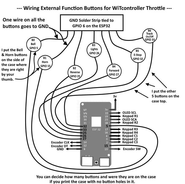
The wiring for the function buttons on the outer part of the case is simple. Run a wire from one side of the button switch to the negative solder pad and the other wire goes to a GPIO pin on the ESP32. You can wire up to 7 of these and use any pin you want. You will tell the software later in a config file which pins are active and which pins go to which button switches. At this point just keep track and write it down. I went from one side of the case to the other with the wiring as shown above.
I forgot to take a picture of a single switch wiring but it is simple. Take a black wire (I used 30 awg for this and the keypad) and hold one end on the solder pad and stretch the wire to where the button switch will be. Add and inch or so and cut it off. Tin the ends and only solder the end to the switch for now. Take a colored wire and stretch it from the pin of the ESP32 it will go on and pull it to where the button will be and cut it a little longer, tin it and solder the one end on.
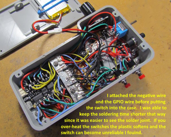
Now put the switch in place and solder the other ends of the two wires to the solder pad and ESP32. Before I soldered with the switches in place. It is hard to see how the solder joint is going on the switch and I probably left the iron on too long and damaged the switch. These are cheap switches (check them with an ohm meter before using – I've found a few that didn't work well). With the switch out you can make the two solder connections very fast and avoid switch damage.
Take your time and work on one switch at a time. Looks like a lot of wires but it goes quickly and you become better at soldering.
.
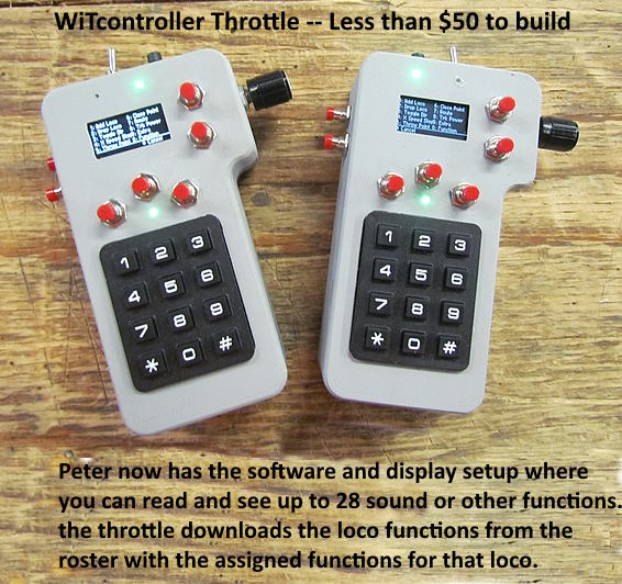
Love the throttle, especially after Peter changed the software so that it sees not only your locos on your roster but brings along all the labels for the sound functions for that loco. You can see up to 28 of them on the screen at any time and toggle any of them on or off . A great feature that some expensive throttles don't have I believer.
=============================================
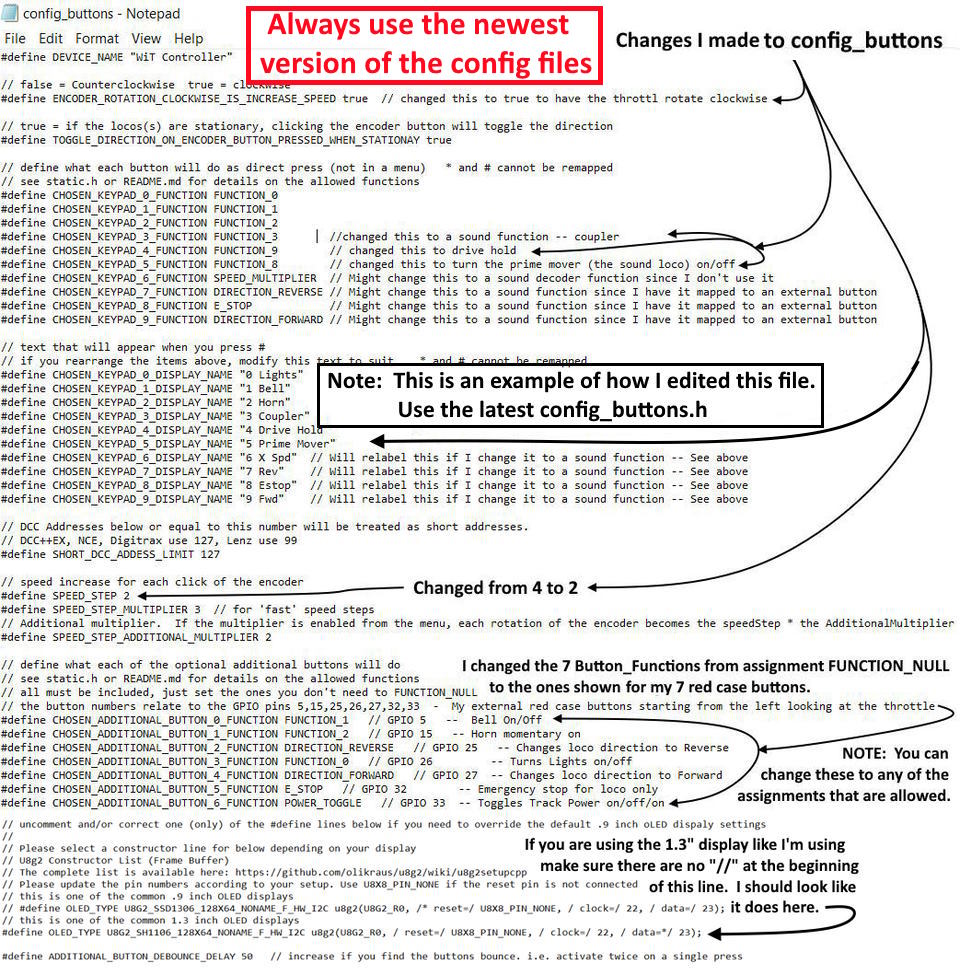
Note: As the WiTcontroller software evolves the following two config files will probably change so these are only examples of how they can be edited at the time I'm writing this ( June 3rd, 2023). Always use the latest ones and follow Peter's instructions on them.
There are default functions that are in the config file shown above and next but with those config files you can change them using notepad to edit the files. Above you can see that I changed some of the assignments and labels for the keypad. Then I assigned the exterior case buttons to a corresponding GPIO pin and and to an assignment/function. I also was able to add label for each of the 7 inputs. The label show up on the display so you know at any time what each button or key on the keypad does. Press the '#' key on the keypad and you see the assignments. The '*' usually takes you to a relevant menu for where you are at the time.
Note that if you are building with the case shown here and the 1.3” display I used you will need to make sure the one line near the bottom does not have the “//” at the beginning of the line. If you are building a throttle with a case with the .96” display leave the “//” on the line. The display will then probably work fine but if not you might have to use another 'constructor line' for your display. I'd strongly suggest getting either the display I used or the one Pete used that are in the part list ( HERE ).
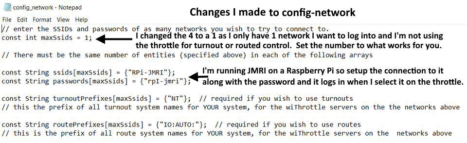
The config_network.h file can also be edited so that the throttle finds your WiFi hotspot and will logon. I have mine set to my hotspot on my Raspberry Pi running JMRI. If you don't do this it will find available networks and you can logon to them using your password. I'm not using the turnouts and routes that show there so didn't edit them and can't help with that if you do.
It takes me about 4 hours and way less than $50 to build one of these ( No do not ask me to build one for you) and the end result is a great throttle. I really like my phone throttle with a added on physical throttle knob shown and described ( HERE ) but now this is my go-to throttle for sure. Peter is also adding more features to it all the time. I'd recommend building it but if you aren't familiar with Arduino's and putting sketches (software) on them and haven't soldered much this is a more advanced build. A great way to learn about these things but could also possibly be a disappointment if you don't have the patience to get through the learning curve. There is help ( HERE on Discord) pretty much 24/7 so give it a go.
=========================================
...........................On..............e......... Return to WiTcontroller Menu