.................................. Return to Sumner's Home Page....
Return to N Scale RR Main Menu........ Return to DCC++ Menu
=========================================
..............Previous Page..............................Next Page If There Is One
=========================================
…...................................--- WiTcontroller Throttle ---
.................... --- GPIO Inputs Part 3 ---
============================================
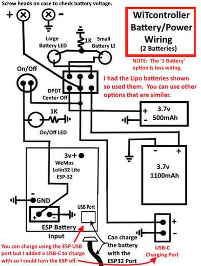
Time for you to make some decisions on your battery circuits. The circuit can be as simple as a wire from the backside of the battery port on the ESP32 to a battery. Plug a USB cable into the ESP32 and it will charge the battery. Then clicking/holding the encoder button will turn the ESP32 on or off. Not sure what the drain is on the battery when it is in standby as I've only used the option shown below where the ESP32 is disconnected from the battery by the push button on/off switch or the center off position of the toggle switch that lets one run one or two batteries as mentioned next.
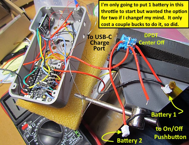
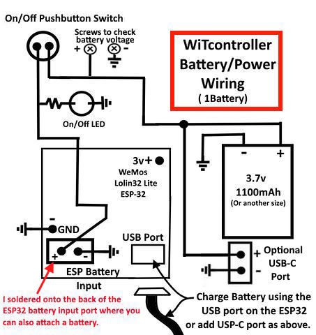
Or you could wire it up like the next drawing with an On/Off switch in the positive wire between the ESP32 and the battery. I put two batteries in the first throttle build and even though I'm only putting one battery in this one to start I wired it for two as it is pretty simple to do that (second image down). If I want to add a second battery later it will be a matter of securing the battery in the case bottom and connecting it to a connector that is there. A couple minute job.
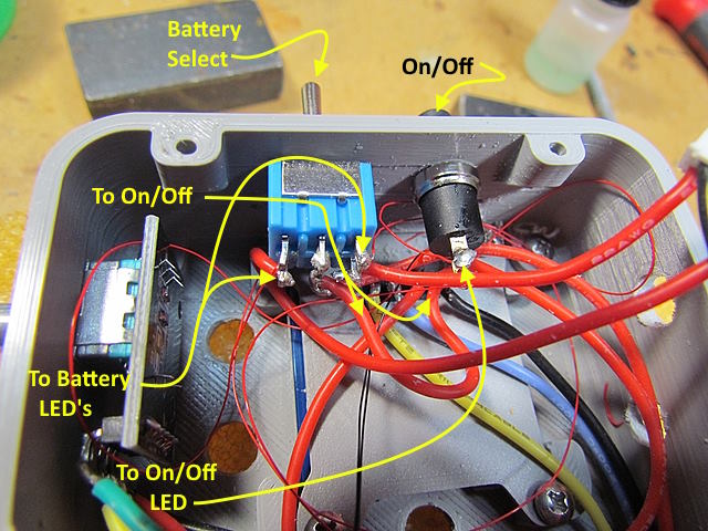
I also installed a battery selector switch and indicator LEDs. I know which battery I'm using and which one is being charge and the cost was minimal and probably added another half hour to the build.
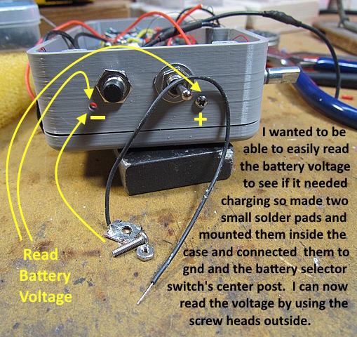
One other item I put in both throttles is a way to read battery voltage. I made two small solder pads and put a black negative wire on one and a red positive on the other. Screwed those to the front wall of the case with the screw heads on the outside of the case. I can take a multi-meter and put it on the screw heads and see charging condition and/or battery voltage easily. Again something that is an option.
Above is one way you can wire in one battery and have and On/Off switch and an On/Off indicator LED and an indicator if the battery is also on or being charged along with a dedicated charging port.
Above is how I wired both of my throttles but there are numerous options.
Again I'm doing my soldering outside of the case.
Not easy to see but the two battery related LEDs are wired to the top two posts on the DPDT Center/Off toggle switch and the ESP32 On/Off indicator is wired to the side of the On/Off push-button switch that is not connected to the battery.
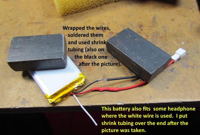
Try and find a battery/batteries that have a flat shape to them.
Above you can see one of the voltage check screws is in and the other is about to go in.
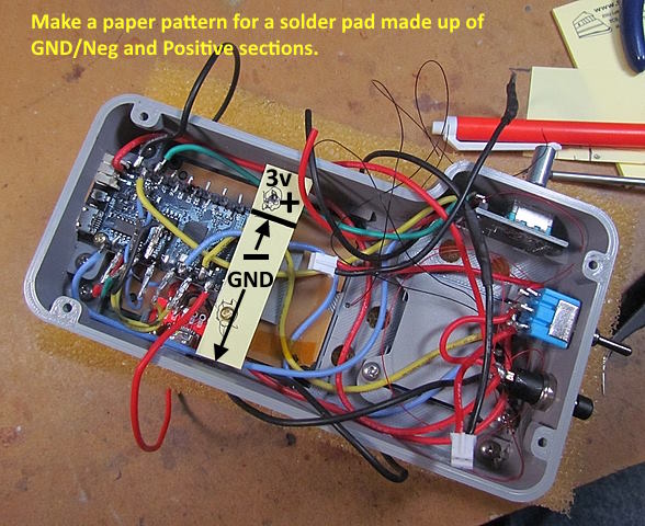
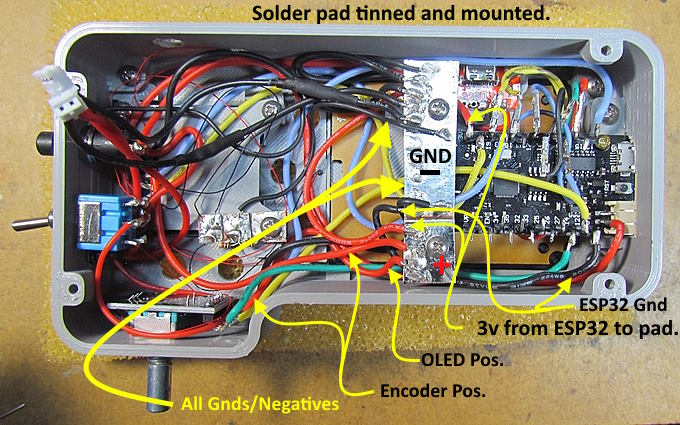
Above we are making a simple pattern for a solder pad with two pads on it. One for 3v ESP32 power out and the larger side is for all the negative leads with one of them between the solder pad and the GND/Negative header pin on the ESP32.
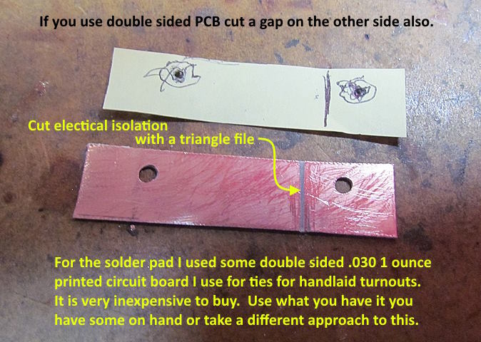
I think I got about 4 or more 4”x 4” printed circuit boards on eBay for about $8 delivered. I use them mainly for PCB ties for handlaid turnouts. There are other options that the solder pads but they sure work great and I use them in various situations.
.
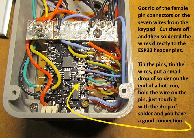
Above you can see that I redid the wires from the keypad to the ESP32 header pins. I'm much happier with them attached this way and it was easier and quicker to do vs. what I had done.
I also loaded the software and fired up the throttle before putting the button switches in. The display didn't come on. Found my wiring error and corrected it as you will now see the two wires from the OLED to the ESP32 have been reversed on the ESP32.
.... continued on the next page............
=========================================
...........................On..............e.........Next Page If There Is One