.................................. Return to Sumner's Home Page....
Return to N Scale RR Main Menu........ Return to DCC++ Menu
=========================================
...............Return to WiTcontroller Menu.............................Next Page If There Is One
=========================================
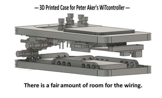
….......--- 3D Printed Case for Peter's WiTcontroller Throttle ---
................................... --- Parts 1 & 2 ---
…...................... --- 3D Case Design by Sumner ---
WiTcontroller is WiFi wireless throttle software designed by Peter Akers of EngineDriver fame. Using Peter's software and his parts list one can build a standalone wireless WiFi throttle that can connect to a wThrottle Server (JMRI, DCC-EX and many others). Peter has written the software and lists the parts needed to build the throttle but it is up to you to come up with a case.
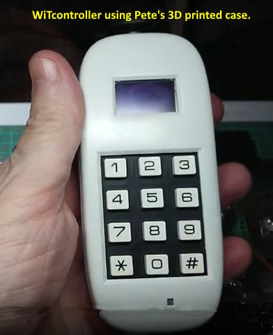
Here is a link to the GitHub info ( HERE ) and to a video showing the throttle in action ( HERE ) using the 'other' Peter's 3D printed case ( peteGSX ) shown in the next image.
A link to Peter's case shown above ( HERE ) and the print files. This is a nice case and a throttle that you can work with one hand which can be handy so I bet a lot of these will be printed and used.
I wanted to try a case with the throttle knob on the side vs. the end or the top and wanted some room for additional function switches so set about designing a case with those features. After a couple days I'm close to printing the case. I probably should of held off posting this until I had a successful print and a working throttle but posting will probably keep me moving on.
I was drawn to this throttle since it will have a number of features that EngineDriver also has (is not a clone of ED thought). It can also be put together for well under $50. I'll still use EngineDriver with my Android phone and the additional physical throttle knob but see this throttle having advantages in some ways over using the phone throttle in some situations. Since the throttle is inexpensive to build I'll have both types giving me a second and maybe a third throttle if I have someone else show up at the layout.
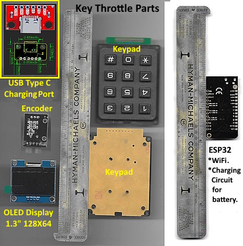
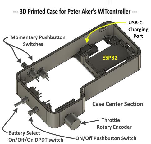
The basic parts that are needed aren't many and are shown above. A Screen, an encoder, a keypad and a ESP32. The USB C charging port is an option I want to try and is not needed in the build. For a basic build the other 4 items are all you need and are quite inexpensive.
I laid the parts on my printer/scanner and scanned them with a ruler next to them for size and so that I could calibrate them in Fusion 360. I can bring the image up in Fusion and in just a second calibrate it using the ruler and then pretty much design the part over the image in Fusion. This gives me pretty accurate parts to use in the design of the case. Once printed I might have to go back and tweek the print a bit after using the real part in the printed case.
Here is a parts list for what I used and some links that might not stay active but from this you can do other searches:
ESP32 – $6.00 ( HERE )
Keypad – $5.00 ( HERE )
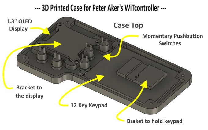
OLED Display ( I went with a slightly larger display at 1.3” vs the .96” used in other builds. The Smaller is cheaper) – $9.00 ( HERE )
Encoder – $2.50 ( HERE )
USB-C Port (not required) – $2.00 ( HERE )
NOTE: I bought multiple of some of those items as if I like the throttle I'll probably build at least one more.
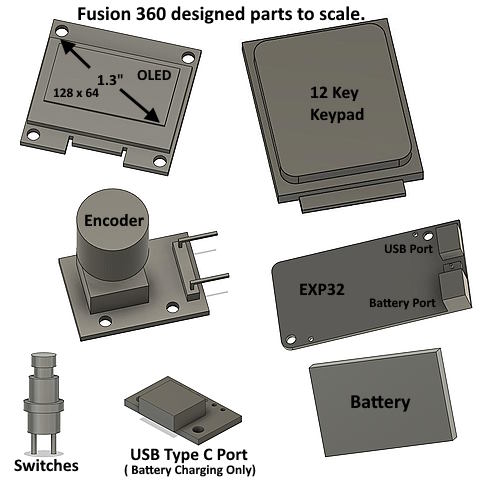
Above are the parts designed with Fusion 360. I could print these out but only need them to design the case as they help me in making sure things will fit as planned.
I have the case designed above and next as I write this but haven't printed it out yet. Still want to fine tune a few things before that. Then most likely I'll print it and then have a few more adjustments that will be needed. Sometimes things are right the first time around but that is rare.
I'm still debating on how I'll mount the battery but it is only about 1/4” thick so even though the case is only 1 1/4” in depth there is a fair amount of room inside for the wiring as all the components minus the battery are shown above.
Continuing on I decide to make some changes ....
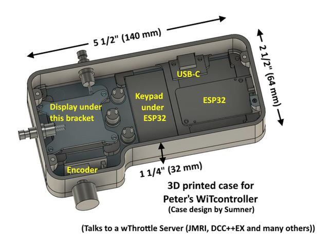
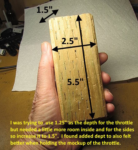
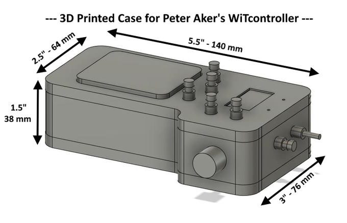
In the previous images I was going with a 1.25 inch thick throttle and things were getting tight putting in what I wanted. I had cut a 2 x 4 down to the size I was shooting for to begin with minus the side extension to move the throttle know out some. Going back to it I liked the 1.5 inch thickness of the 2 x 4 and felt I'd like it better grip wise than if I went with 1.25 inches. So I changed the center section to 1 inches and left the top and bottom parts at 1/4” (sorry about no metric but I have to convert all the time the other way and don't want to take the time to look up all the right values changing inches to mm).
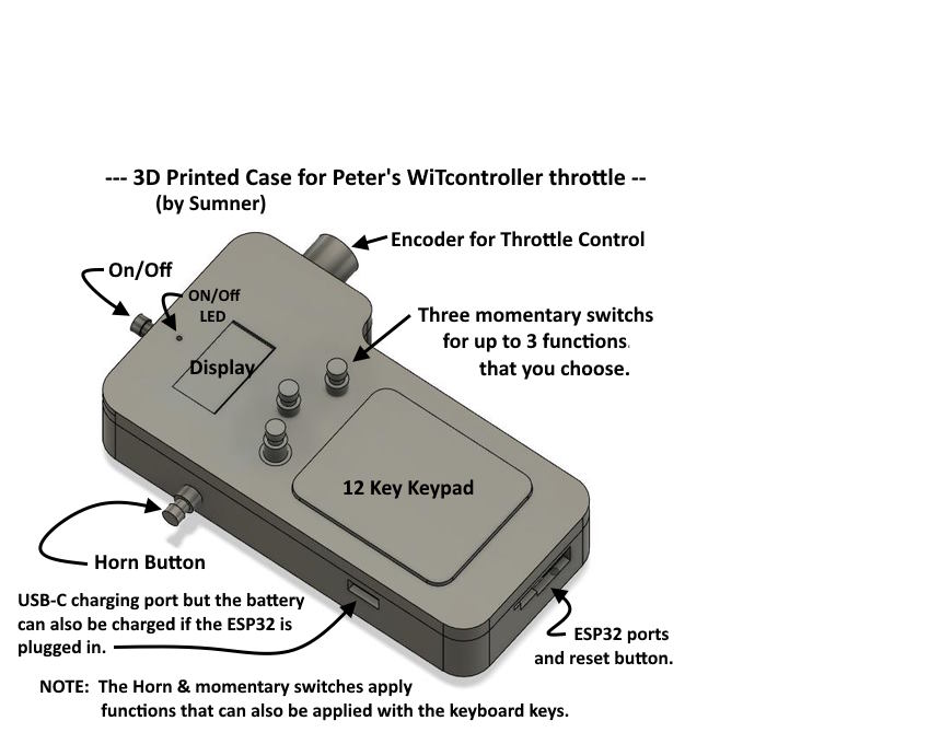
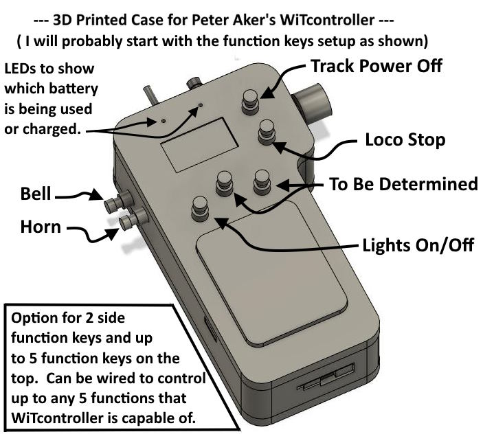
In the picture above and in the following ones you will see a number of momentary pushbutton switches that can control different functions. Any of these functions can still be controlled by the keyboard so you don't need to build the throttle with them in place. I'll end up with two print files. One with all the holes like how I'm going to build the throttle and another set of files where there will be .060” holes in the same location. You can drill them out or fill them in or leave them.
.
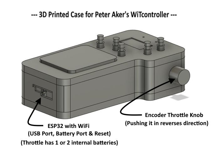
The ESP32 has a port on the end for connecting it to a battery and if you plug 5v into the USB port the battery will take a charge. I plan on wiring to the back side of the battery socket and wiring to the battery (2 in my case) that is on board. I'm also adding a USB-C charging socket on the side out of view above. It will be used to charge the battery/batteries. I did this so I could move the ESP32 to the back edge of the case. This will allow easy connection to a computer via a USB cable for software changes over time. Also I'll be able to toggle the 'reset' switch if needed and a battery could be connect to the original battery socket if for some reason one wanted to do that.
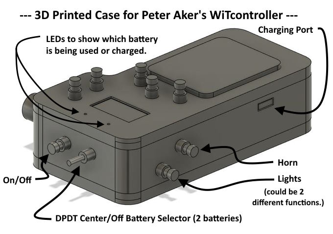
I plan on wiring up 5 of the 7 function keys to start with as shown above. I'll hard wire the keys to the keys on the keyboard contacts for the functions shown. If I understand Peter's documentation correctly you can reassign the keys, thus the pushbutton switches to other functions by editing the config_buttons.h file. I'll probably wire the 2 'To Be Determined' buttons to keyboard keys 4 and 5. Peter has them set to 'Function 4 & 5'. They can be assigned with the config_buttons.h file at any time to one of the 15 assignments that Peter has available at this time shown ( HERE ) at the bottom of the page.
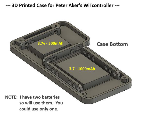
I have two batters so figured use them, why not? I'm hoping to secure them with zip-ties across the ends and tops using the holes in the brackets on either side of the battery. I'll have some short leads on the batteries with JST connectors on them and then leads going to the DPDT toggle switch with other JST connectors on them That way I can connect the bottom of the case with the batteries when I finish the wiring in the other two case parts and want to put the bottom on and it won't be in the way prior to that.
I have no idea at this point how long the throttle will run on say the 500mAh battery he is using but I imagine quite a while. To run two batteries I only need to add the 'battery select' DPDT Center Off switch at the front of the case. I'll have two LEDs on the top of the case so I can see which battery is being used or charged. This is not a requirement by any means in building the throttle. I imagine most people will only use a single battery. If that is the case you don't need the DPDT toggle switch and in fact Peter doesn't use a on/off switch as far as I can tell.
Clicking the decoder turns the throttle on from I guess a sleep mode. I have no idea how lone it will run on the sleep mode. I'm using an on/off pushbutton switch to turn off all power since there might be times I don't use the throttle for days at a time. I'll know more about all of this if I can finish the build and see what happens in real life so if you are building a throttle before then do your research, don't count on mine.
.
.
.
There is quite a big going on in the throttle but if you looks at Peter's wiring schematic ( HERE ) you will see there isn't a lot of wiring involved. I'll have more since I want the pushbutton function switches. There is about 3/4's of an inch of room down the whole case for wiring so I think it will all work out. Should know a few days after writing this.
To be continued...............Add
=========================================
...........................On..............e.........Next Page If There Is One