.................................. Return to Sumner's Home Page....
Return to N Scale RR Main Menu........ Return to WiTcontroller Menu
=========================================
..............Previous Page..............................Next Page If There Is One
=========================================
….......--- Building Peter's WiTcontroller Throttle ---
.............................. --- Part 2 ---
=========================================
Parts List:
The parts used for building the throttle can be obtained from a number of sources. The keypad and display need to be source so that you end up with parts that will fit PeteGSX's case, my case, your case or someone else's. There are a number of ESP32's out there and I'm not familiar with them and unless you are I'd stick with the one that Peter used or I used (the same one) as it works for sure. Peter is in Australia and I'm in the States so we source parts from different sources.
The following are the parts that Peter used along with PeteGSX's 3D printed Case (From Peter's GitHub account ( HERE ).
WeMos Lite LOLIN32 (ESP32 Arduino with LiPo charger) (Example)
3x4 Keypad (Example)
Polymer Lithium Ion Battery LiPo 400mAh 3.7V 502535 JST Connector (or larger capacity) (500mAh Example)
KY-040 Rotary Encoder Module
OLED Display 0.96" 128x64 Blue I2C IIC SSD1306 (Example)
PeteGSX's Case you can print - ( HERE )
Knob (Example)
The following are the parts I used for 'my build' You might want to use them or not. If you are going to print my throttle case I'd get the same keypad and OLED display to make sure they fit. If you go with a 0.96” display it will be smaller than the window in the case. You can find these items numerous places:
3x4 Keypad (If you are going to print my case I'd get the one in the link to make sure it fits) – $5 each – ( HERE ) (I ordered two so I can make 2 throttles)
Lipo battery (the links are the two I'm using but lots of options here although for my case I'd get a flat one like in the links) – $10 & $16 – ( HERE ) & ( HERE )
Rotary Encoder Module – $10 for 5Pcs -- ( HERE )
WeMos Lite LOLIN 32 (ESP Arduino with Lipo Charger port – $16 3Pcs -- ( HERE )
OLED 1.3” Display (I went with a 1.3” vs. the 0.96” that Peter used and I'm happy with it) – $9 -- ( HERE )
DPDT On/Off/On Toggle Switch -- $7 5 Pcs -- ( HERE )
SPST Momentary Pushbutton Switches – $8 10Pcs -- ( HERE )
SPST On/Off Pushbutton Switch -- $10 5Pcs -- ( HERE )
USB-C Port -- $8 for 5Pcs -- ( HERE )
My 3D printed case print files ( HERE soon)
A number of the items like the switches I already had as the result of ordering parts for other projects. Since I ordered 2 keypads I'll probably build a second throttle as I also have all the other parts needed as shown above.
=========================================
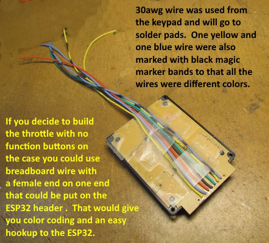
Let's put a throttle together. If you solder pretty good you can do this in an easy day but take your time and so that it works the first time. Also it is your choice if you want the extra (besides the keypad) function buttons and how many. You can print a case with or without them. If you decide to go without I'd suggest thinking about still printing the case with the holes for the function buttons in it. Then get some decorative plugs to plug them. In the future if you wanted some function buttons pop the plugs and put them in.
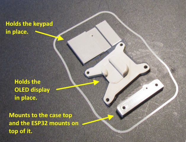
In total there are six parts that need to be printed. The case top, middle, bottom and the three other small components shown above.
.
.
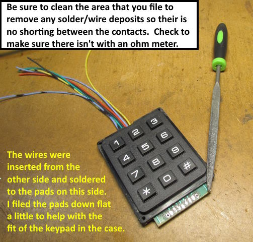
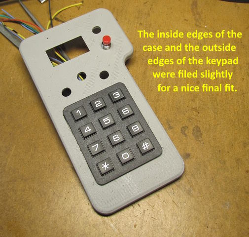
I kept the tolerance on the print tight and printed on 'Standard' quality using Cura as the slicer and an Ender 3 Pro filament printer for the printer. I spent a few minutes on the the fit of the keypad and the holes for the button switches using some small files.
.
.
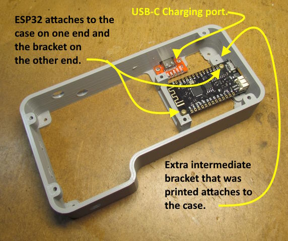
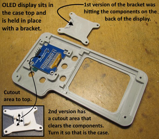
The first bracket I designed to push against the OLED display and hold it in place was pushing on some of the components on the back of the display. I then designed a second one (bottom left above) that still pushes on the display but not the components. Orientate so that it is not pushing on the components when it is screwed into place.
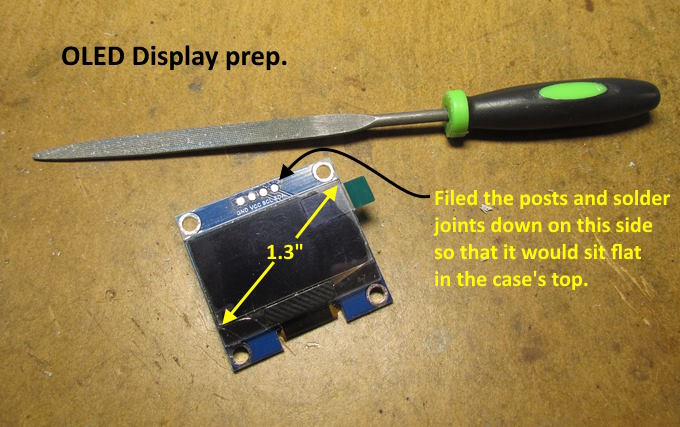
When your are at the step above or before it I'd suggest soldering some wires to the pins on the OLED display. Above the pins are still straight. I bent the tips slightly backwards before soldering the wires on. Support the bottom of the pin so you don't exert pressure on the display itself. I wait until later but it would be easier to do the soldering now or before this. Make the wires 5-6 inches long and cut them to length later in the build.
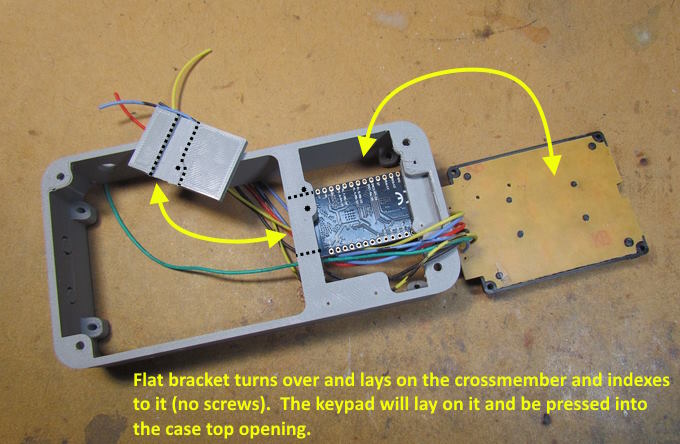
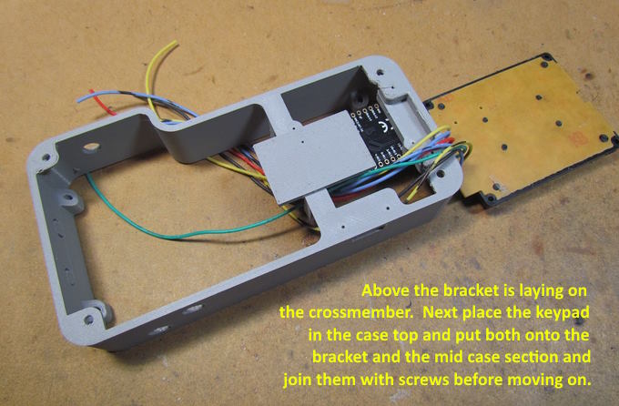
The flat bracket shown above has a cutout in it that matches the shape of the cross-member. When you lay it in place as shown in the next photo make sure it is indexed onto the cross-member properly. It sits in place and isn't screwed into place.
Similar to the bracket that pushes on the OLED display this one pressed against the back of the keypad and holds it in place on the backside of the case top once the top is screwed to the mid-case section.
To be continued.........and if you came into this build here click ( HERE ) to go to the start of the build....Add
=========================================
...........................On..............e.........Next Page If There Is One