..........................…………......... Return to Sumner's Home Page....
………….Return to N Scale RR Main Menu........ Return to DCC++ Menu
=========================================
.………….......Previous Page.................…………………..........Next Page If There Is One
....=========================================
….............…...……....--- DC & DCC Sound & Loco Controller Build ---
....=========================================
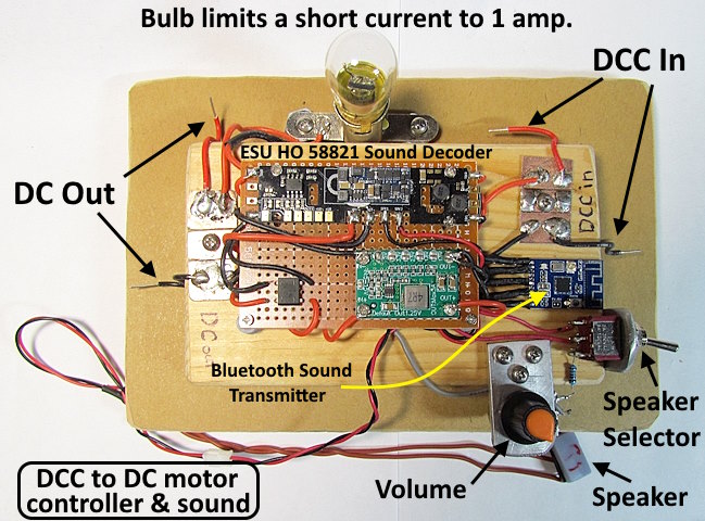
NOTE: Can control a DC loco on a DCC layout and can provide sound for a non-sound DC or DCC loco.
-------------------------------------------------------------------------------------------------------------------------------------------------------------------
On this page I’ll show you how to build your DC & DCC Sound & Loco Controller.
Parts List:
ESU 58821 HO Sound Decoder ……………………………………….…… $101.00 Streamlined Backshop ( HERE )
DB107 Bridge Rectifier …………………………………………….………. 50 for $7 Amazon but not available now but others ( HERE )
HiLetgo MP1495 stepdown buck converter …………………………….… 5 for $8 Amazon ( HERE )
KCX_BT_Emitter V7.1 transmitter ………………………………………. $1.43 AliExpress ( HERE ) (Also from Amazon but maybe not now)
500K Volume Controller …………………………………………………… From my parts drawer.
100K Resistor………………………………………………………………… From my parts drawer.
Speaker……………………………………………………………………….. Digikey
Speaker Enclosure ………………………………………………………….. 3D printed
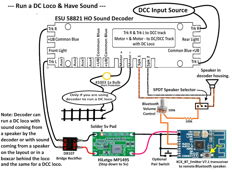
Lets start off with the wiring diagram….
The wiring is pretty straight forward.
I bought the decoder from Streamlined Backshop (HERE) but other suppliers also handle them. I had them put a GP7 EMD 567 prime mover sound file on the decoder since a number of engines in my time period had that prime mover. You could use a sound file of your choosing. The DB107 bridge rectifier, MP1495 module and the KCX transmitter came from Amazon and bought more of the transmitters from China since I’ve burnt some of them up testing/designing. The 500K pot and other 100k resistor limit the current to the KCX_BT_Emitter, without those you will burn it up. The speaker in the boxcar and with the controller are from DigiKey. Speaker enclosures I 3D printed with print files (HERE). I’ll list the parts for the boxcar later in the build.
.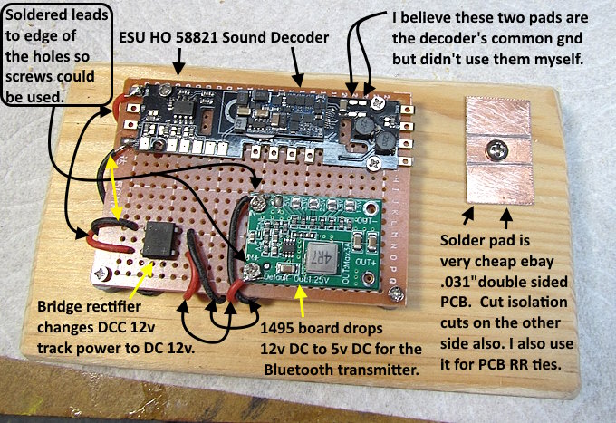
Not using the small perfboard above for much except to hold the parts. The wires to and from the bridge rectifier are soldered to it under the board. There are ring holes on the left side of the 1495 board where you solder the input wires to. I soldered the wires to the edge of those rings so that I could use two M2 threaded screws to hold the board to the perfboard and wood under it. I like to use solder pads as it is easy to attach multiple wires in a small space and easy to solder them on or off. I use .031” double side boards as I also use them for PCB ties building N scale turnouts.
Since the screw is isolated from the end pads you don’t have to put gaps on the underside of the PCB but I do anyway. Always keep in mind though that the screw can carry current to the underside of the board which can at times be a problem. Isolate that side if needed.
.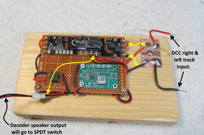
The wire (bottom left) will go to a SPDT switch used to select the speaker output. I used a connector (while testing) but the wire could run directly there without the connector.
.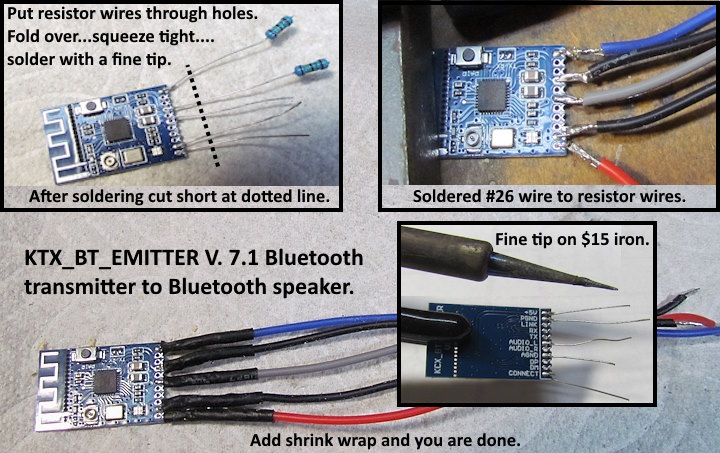
The hardest part of the build can be soldering the wires to the KTX transmitter module. I’ve tried different ways and the method above is by far the easiest. Trying to solder a wire right to it is hard as the pad spacing is very close. I found the best way was to cut wires from resistors (I have hundreds that I’ll never use). Make a hook in the end of the wire and run it through the hole on the KTX. Flatten it with some needle nose pliers. I put liquid flux on with a micro brush. I then use a fine tip iron as hot as it goes and some very thin solder (.3 mm). Put a little drop of solder on the iron tip. Get on the wire & pad and off as soon as you see the solder flow.
Cut the wires short (see image above). I soldered #26 wire to the short resistor wire. I’ll put a larger blob of solder on the iron tip and hold the wire against the side of the resistor wire and drag the solder along the two wires and off. After doing it a time or two you will get the hang of it.
.
When I was doing the first test I burned the KTX Bluetooth transmitter up with evidently too much current going to it from the decoder’s speaker output wire (surprised me). Then I added some resistance to the circuit (100k not 100 ohm) and had no further problems. The audio gnd attaches to the boards gnd and both of those attach to the gnd on the 1495. Above the audio gnd wire attaches to the other gnc wire between the KTX and the 1495. Later I soldered both wires to the 1495 (either will work).
.
I’ll end up with a 9x16mm or a 9x25mm speaker with a larger enclosure. The 8x12mm shown here is OK but the sound will be better with a larger speaker and larger enclosure.
.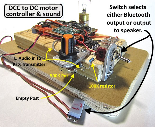
Make sure the resistor from the selector switch to the volume pot is 100K and not 100 ohm . The volume control pot is 500k.
.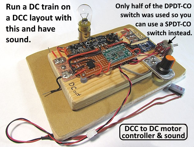
I used a DPDT-CO toggle since I had one but the poles on one side aren’t needed or used so you could use a SPDT-CO if you have one.
The next page will document the Bluetooth boxcar build .....
=========================================
...........................On..............e.........Next Page If There Is One