.................................. Return to Sumner's Home Page....
Return to N Scale RR Main Menu........... Return to Building UP's Canyon Division Menu
=========================================
...............Previous Page.............................Next Page If There Is One
=========================================
… ..…-- Main Yard Control Panel Part 1 ---
============================================
Took a break from layout construction and worked some on a problem I've been laying awake thinking about when I wake up a 3 am.
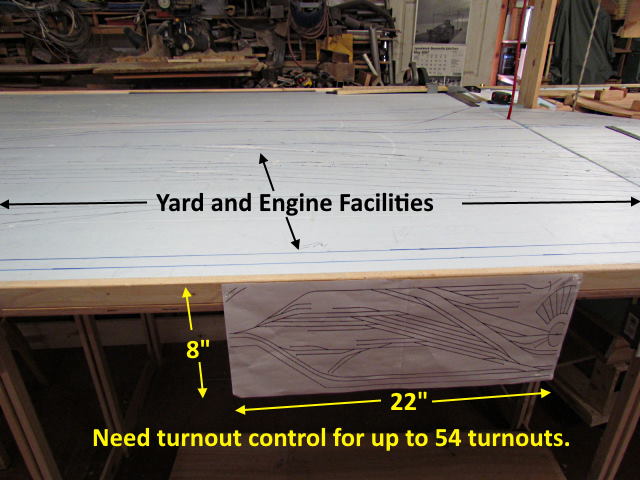
The main yard and engine facility part of the layout will have over 50 turnouts if I get them all installed (I've built over 40 at this point that I can use). The area is about 30” wide and about 12 feet long from the beginning of the yard on the east end to the roundhouse on the west end. I thought a central control panel would be really crowded with the track diagram and trying to get the switches needed to control all of the turnouts so decided against that approach.
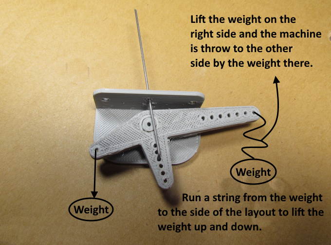
I really like my 'Gravity Switch Machines' shown above and described ( HERE ). They are super simple, simple to install, very reliable, no wiring to run except to the frog and cost about nothing if you have a 3D printer but didn't want 50+ activating lines under the layout in this area along with the fact that they take up too much fascia space to fit the area. I'll still use them a number of other places on the layout but not here.
Instead I'm going to probably use servo control and my servo mounts, switch boxes and servo controllers all shown and explained ( HERE ). It works well and is also easy to install and costs less than $10 total per turnout.
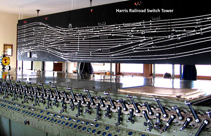
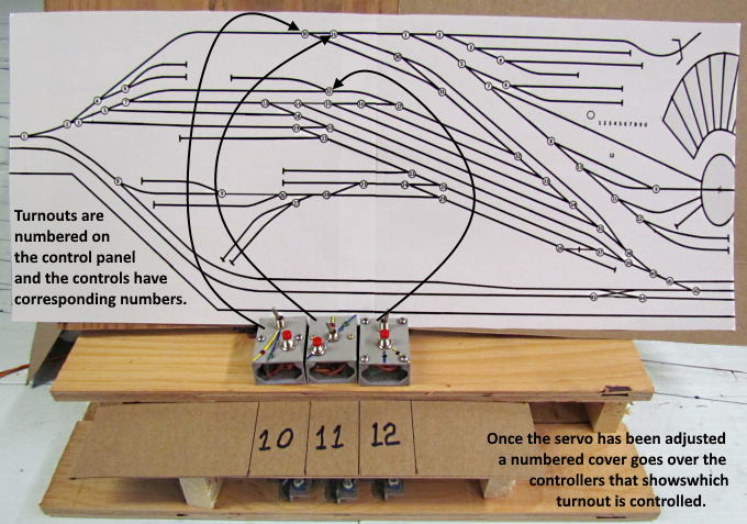
After seeing the picture above and ones similar I thought why not use the basic principal of its approach to handling the turnouts in a yard. Have a diagram of the yard above and the turnout controls separate from the diagram. Above the controls are below the diagram. In my case I'll probably run them off to either side of it.
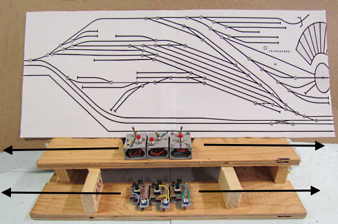
Above the basic concept is shown. The track diagram is about 8” X 21” in size and represents the yard and engine facility area. At each turnout there is a round circle with a number in it. Running off to either side of the diagram (above it is shown below) will be a row of switch boxes with the servo controller for each located below and in front of the switch box.
At some point I'll put up how easy it is to design and print out one of these track diagrams if there is any interest.
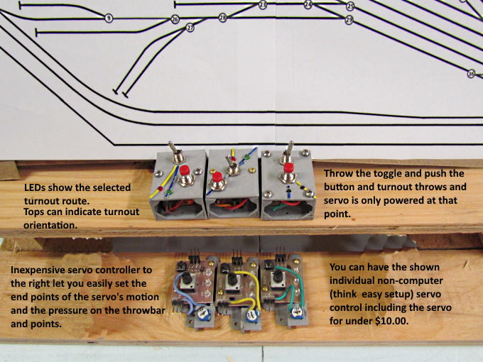
For the purpose of checking this out I grabbed some switch boxes I had on hand and three servo controllers. The tops of the switch boxes I'll use will have a representation of the turnout it controls with the appropriate routes shown on it similar to what is shown above. More on those options ( HERE ) but I'll be making up more that look like what the route looks like on the track diagram.
In addition once the servo controller has been used to set how far the servo throws the points (you can easily adjust the pressure of the points on the stock rails) a cover will be placed over them that has the number of the turnout that the switch controls.
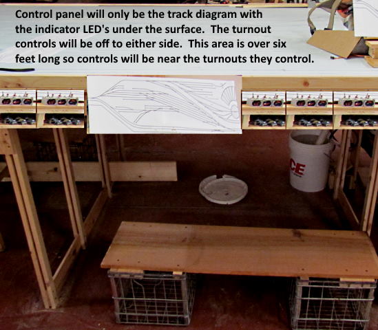
The track diagram will be in the middle of the area with the turnout controls running off to both sides. Since the length of the area is about 12 feet the controls will be very close to the turnout they control.
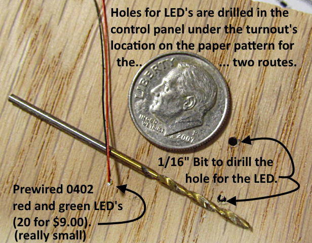
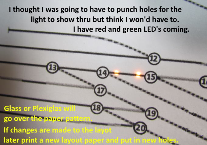
In addition the track diagram will have indicator LED lighting to show the current position that the turnout is in. I tried out some 0404 white LED's that I use for decoder installs and liked the effect and ordered green and red ones. The green ones will be used on the through route and the red on the divergent route.
These are really small LED's and I'll probably use a smaller bit for the hole than what is show. I had some 1/4” plywood paneling left over from a camper I built and will use it for the control panel backing. The paper track diagram will lay on it with cleat Plexiglas over it. If I need to make changes I can drill new holes and use a new paper track diagram.
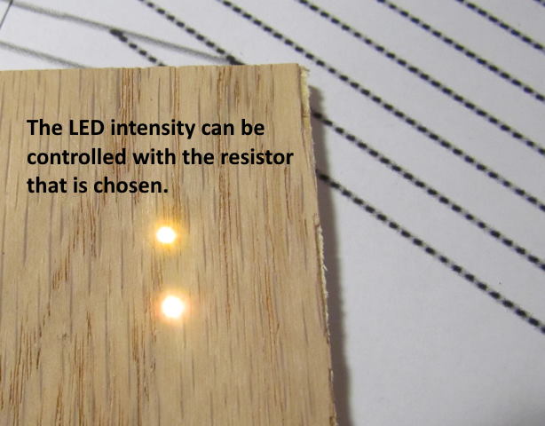
Above is my test run of seeing what the LED's look like mounted in the plywood. You can vary the intensity with the resistor value you use.
I thought I'd have to punch holes in the paper for the LED light to shine through but even with the bright lighting in the shop I could easily see the LED through the paper track plan. I'll see how the green and red show up before making a final decision.
There will be two sets of lights. On set on the switch boxes and the second set on the track diagram. A quick look at the track diagram should show one the route that is currently active with how the turnouts are currently thrown.
To be continued, but first I have to get back to creating the layout's upper level and it will be quite awhile before I'll need this control panel but at least getting this far might help my sleep …..........
If you came into the build here you can find the main index for the build ( HERE ).
=========================================
...........................On..............e.........Next Page If There Is One