.................................. Return to Sumner's Home Page....
Return to N Scale RR Main Menu....... Return to Building UP's Canyon Division Menu
=========================================
..............Previous Page..............................Next Page If There Is One
=========================================
….......--- Layout Framework Planning ---
=========================================
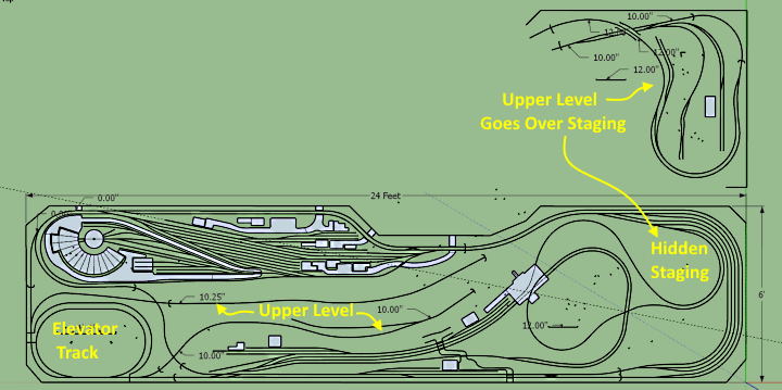
The next image shows the 'kind-of-what-will-be' track plan.
The image top right above is the upper level over the hidden staging. The rest of the upper level is shown to the left. What is show is basically what will be there but changes will be/have already been drawn-up on newer track plans. I won't post them all as I'm sure they will change even when laying track.
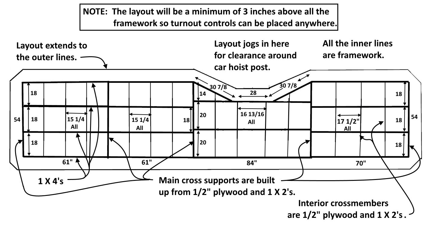
Above is/was my plans for the framework. More pictures of the build will follow (as I write this the far right end is pretty much finished.
I want to use inexpensive and simple to install and control servos in some areas and my 'Gravity Switchers' in other areas. They both need about 2 inches of clearance under the layout. A common problem is having one's framing in the way at times. I hope to get around this as all of the framework shown above will be a minimum of 3 inches below the layout everywhere. The framework is a grid as shown above. I can attach upright supports on any member of that grid. A large area, the yard, the near side and the staging will all be the same elevation. It will consist of risers place anywhere on the framework grid supporting 1/2” plywood with 1” of ridge foam board on top of it 3 inches above the framework. If I have a riser where I want a servo the riser will just be removed and re-positioned away from the servo or gravity switcher.
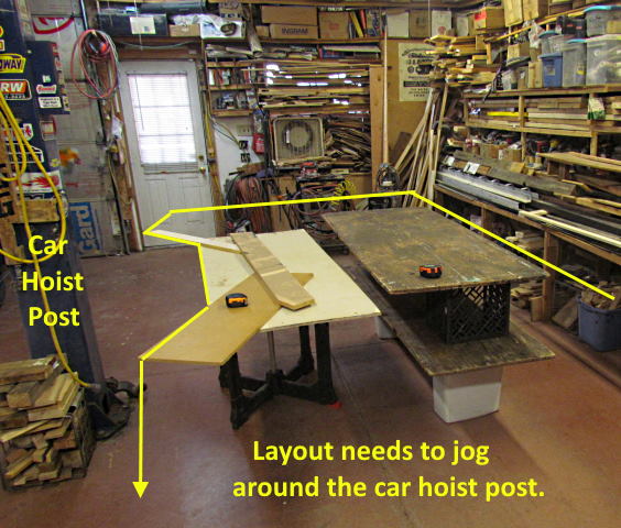
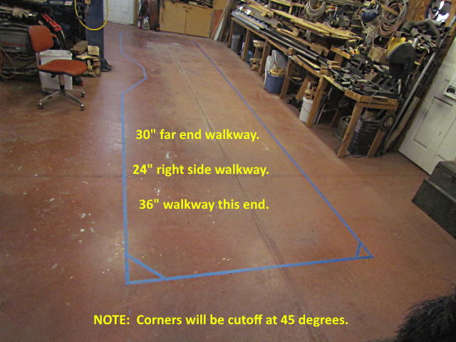
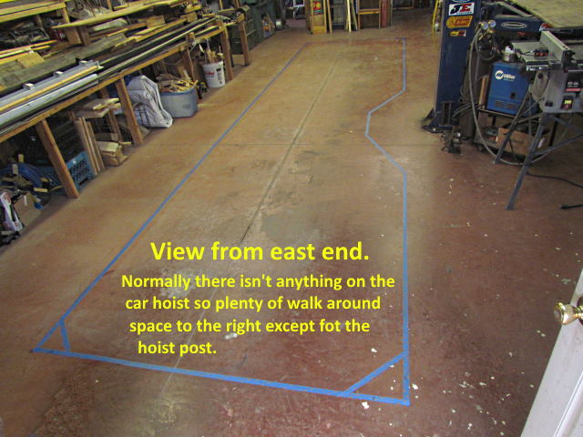
I had to set one part of the layout in slightly to have room to walk around one of the car hoist posts shown above on the left side of the image. Unless a car is on the lift (rarely) I can walk around the left side of that post but still wanted the option of being able to walk around the right side and didn't want the layout right up against it.
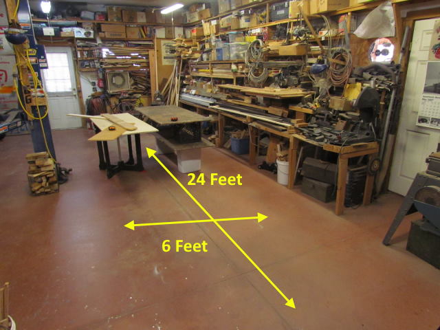
I mocked the layup in the area of the post so I could come up with the measurements for the plans for the layout and the framework.
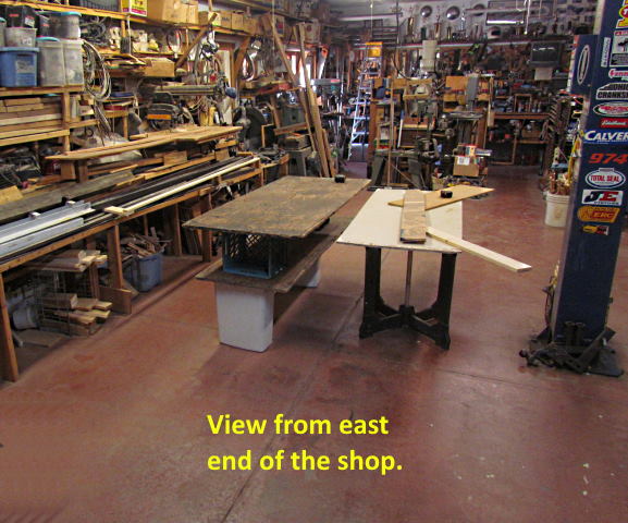
The view above is of the area as seen when you walk in from the street side of the shop.
Next I taped the layout's outline on the floor. The right side might seem tight but I'll be about the only one walking around the layout and I've had less than the 24 inches for all the years I had the race car build in this area so 24” seems huge to me now.
On the next page we will start with the framework build.
=========================================
...........................On..............e.........Next Page If There Is One