.................................. Return to Sumner's Home Page....
Return to N Scale RR Main Menu........ Return Turntable Menu
=========================================
..............Previous Page..............................Next Page If There Is One
=========================================
... --- N Scale Roundhouse Turntable Controller ---
....................The two sketches for the Arduino Nano's are ( HERE ).
=========================================
On this page I'll outline how I'm controlling the turntable. You could use whatever method suits you. You could make it as simple as turning the table manually by hand and using a DPDT switch to reverse the polarity on the bridge track. You also wouldn't need the hand controller shown below. You could use push button and toggle switches at the edge of the layout. You could also pick which operations that would be controlled with those switches.
The following is fairly complex but very doable for anyone who has done much in the way of working with Arduino's and basic wiring. I wrote two sketches to work with two Arduino Nano's.
The two sketches for the Arduino Nano's are ( HERE ).
This was my first experience programming/coding in about 40 years and that was in basic and also my first try at putting an Arduino to work. I pulled parts of the code from other people's sketches/programs and tied them together with some of my own code. I tested with Uno's but went to the Nano's for their reduced size and cost and also like the terminal adapters that they plugged into for their convenience in running the wiring.
The Arduino's are controlled by .....
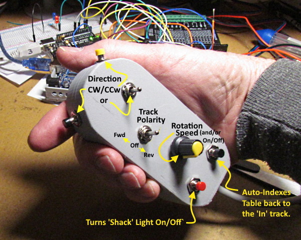
…. the hand controller. There will also be overhead lighting that comes on any time there is track power to the table.
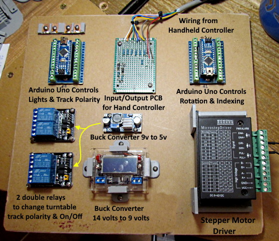
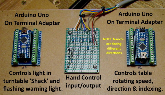
The two Arduino's that are used are connected and interact to some degree. The one on the right below controls the table's rotational direction, speed and can index the table to the 'In' track. To move the table to all the other tracks you manually index the table but it allows for very low rotational speeds since a stepper motor is used for the rotation of the table.
NOTE: Be aware that the two Arduino's are orientated differently on the board to help with the way the wiring runs. Their vertical orientation is reversed.
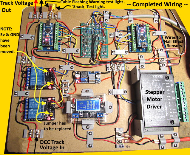
The Arduino on the left below controls a light in the control 'Shack' on the table and also turns on a flashing warning light when the table is in motion (the 'Shack' light goes off when the warning light is flashing.
Between the two Arduino's is a prototype PCB which I'll talk about next. On the left side of the board are 2 two channel relays. You can reverse the polarity of the track on the table using the hand controller which activates the relays using one of the Arduino's. One might be able to use only one but I went with two to make sure there was no shorting when the polarity is changed and they cost less than $4.00 each. These can run off the power from the Arduino but for a few dollars I used an inexpensive Buck Converter to power them with 5 volts.
Below the Buck Converter that produces 5 volts is another Buck Converter that I spent a couple dollars more on that has a display on it showing the output voltage. For power I'm using a 14.5 volt brick power supply I had. The Stepper Motor Driver on the bottom right works on 9-42 volts so the brick power supply powers it and also the Buck Converter with the display. That Buck Converter steps the 14.5 volts down to 9 volts to power the two Arduino's and also the Buck Converter that steps the voltage down to 5 volts for the relays.
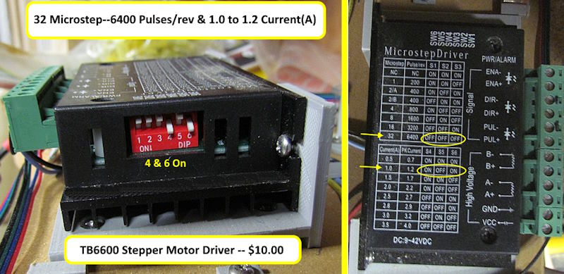
On the bottom right is the Stepper Motor Driver that drives the stepper motor and can step the table into 6400 individual steps per revolution. I had never used a stepper motor or driver but there isn't too much to it. You'll see that the wiring is pretty simple and the sketch running in the one Arduino does all of the controlling of the motor. A link to where I bought the Usongshine Stepper Motor Driver TB6600 ( HERE ).
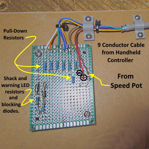
I used a little prototype board to mount the few components that are needed. There are two blocking diodes and two resistors on the lower left side that are needed for the LED's on the table for the 'Shack' lighting and the flashing warning light that activates when the table is in motion. The remainder of the resistors or pull-down resistors for various control circuits activated via the hand controller. The cable is a nine connector cable that I bought off Amazon ( HERE ). If the link doesn't work google Jameco Valuepro SC9-25 Multi-Conductor Cable.
I used a 4 foot piece between the controller and the board and another shorter piece that I pull the wires from to keep the colors the same from the resistors to the Arduino's. It was cheap enough that I got some extra for future projects.
.
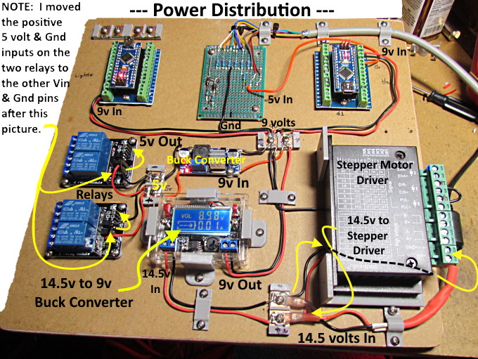
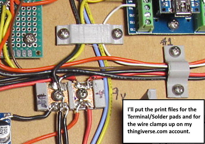
Above you can see the power wires and how they were run from component to component and also to terminal/solder pads. I designed the terminal/solder pads and printed them with the Ender 3 Pro. I'll get the files up on my thingiverse.com account at some point. I'm really happy with how they worked and also how the different wire clamps I designed and printed worked. I'll get those files up also at some point also.
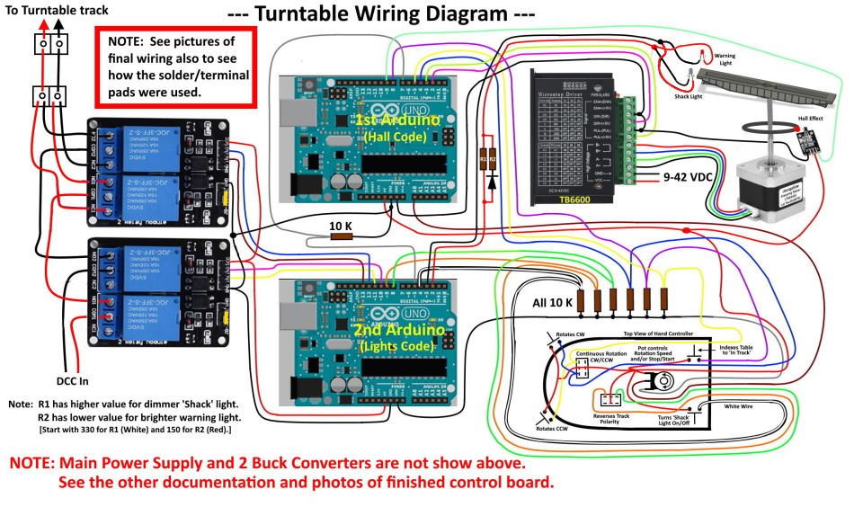
Below a ways you'll find wiring diagram but on it I didn't include the 'power in' and the buck converter wiring and other power wiring so use the above for that if you go this route. All of the components are pretty cheap on Amazon or eBay. You can find the stepper motor driver ( Usongshine Stepper Motor Driver TB6600 ) for about $12.00. Nano's are under $5 each. Same for the relays and buck converters.
Above all of the wiring is finished. It looks complicated but only took a few hours. Start with all the power wires and then move to one Arduino at a time and work your way through it wire by wire.
DCC track voltage enters at the bottom left but I assume this would also work for straight DC?? Power out to the track on the table is at the upper left. Next to the track voltage output is the terminal connector where you connect the wires that go to the 'Shack' light and the flashing warning light. Note that you only need these two wires that run to the table for the two lights. When the power flows one direction through the two wires one light is activated and when the polarity is reversed the other light comes on if activated by the hand controller.
The 'power in' comes in at the bottom right from the 14.5 volt power supply brick I had. You could use about any voltage from 10-12 volts up to whatever the first buck converters will handle.
My power supply is 3 amps but I have the stepper motor driver set for 1 amp (1.2 amp peak) so I believe that a 2 amp power supply would be adequate. The TB6600 is set also for 32 Microsteps (6400 pulses/rev). See the settings via the 'Dip Switch' on the end in the image above.
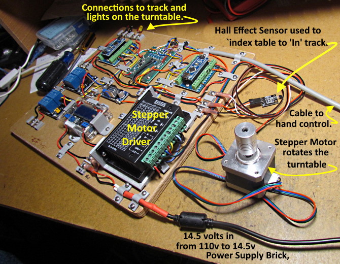
Above the stepper motor driver is a terminal pad for the three wires that go to the Hall Effect Sensor that is used if you want to have the auto indexing to the 'In Track'.
The cable from the hand controller comes in by the cable at the upper right and wires to the prototype circuit board.
Above one can see how the power wires and the Arduino control wires connect. Also connecting on the side of the stepper motor driver is the cable going from the driver to the stepper motor that rotates the table. This wiring is also pretty straight forward.
Above you can see the terminal/solder pads. I designed the terminal/solder pads and printed them with the Ender 3 Pro. You can find the files for the solder pads ( HERE ) and the wire clamps ( HERE ).
I'm really happy with how they worked and also how the different wire clamps I designed and printed worked. I'll get those files up also at some point also. I'll also probably post the brackets I made for the one buck converter with the display and also for the stepper motor driver if there is any interest in those. I also made some small round feet that fit under a number of the boards that have screw holes for mounting but nothing to hold them just off the wood surface resulting in the under side of the PCB's and the soldered components hitting the mounting board.
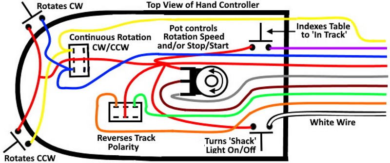
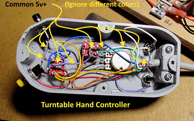
Above is the wiring for the hand controller. The red wire is 5 volt positive that needs to run to all of the push button switches and the toggle switches and pot. You can daisy chain it any way that work for you. I'll also have the print files up to print the hand control enclosure. One could also make one out of something else.
Above is a view of the hand controller wiring. Sorry, I didn't use a common red color for the 5v+ that runs to all the switches and the Pot. I use scraps I had left over. The 5v+ comes in as the red wire that goes to the middle contacts of the toggle just to the right of the yellow push button switch. From there it daisy chains to all the other switches and the Pot. The gray 5v- comes in and goes to the bottom contact on the Pot. The brown connects to the center post of the Pot and is the only analog input from the controller to the one Arduino.
Above is the basic wiring diagram. I tried to stay as close to the wire colors that are shown above as I could. Most of the hand control wires go to pull-down resistors. I used the same wire coloring from the resistors to the Arduino's by pulling the same wires from a short section of the cable.
NOTE:
If it is hard to see the wiring in the photos and diagrams above you can download a PDF version of them ( HERE ) that is easier to enlarge.
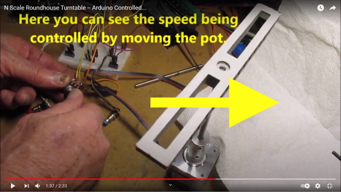
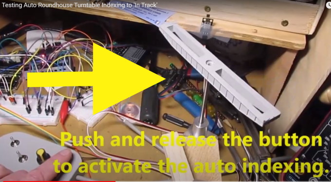
Above and ( HERE ) is a YouTube of the turntable operating via the Arduino's as a test before constructing the hand controller enclosure.
The video above or ( HERE ) illustrates how the auto-indexing to the 'In track' works.
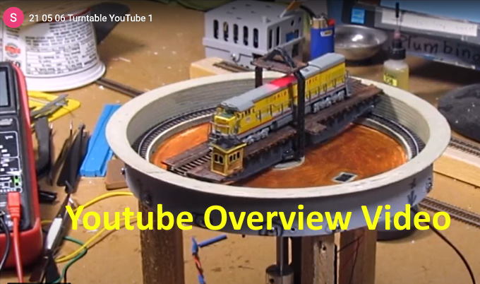
The video above is an overview of the finished turntable and what is controlled by the hand controller. Click on the picture or ( HERE ) for the video.
You can find all the turntable files on my thingiverse.com account ( HERE ).
=========================================
...........................On..............e.........Next Page If There Is One