.................................. Return to Sumner's Home Page....
Return to N Scale RR Main Menu........ Return Turntable Menu
=========================================
..............Previous Page..............................Next Page If There Is One
=========================================
... --- N Scale Turntable Bridge/Deck Wiring Part 2 ---
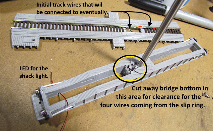
Part 2 of wiring the turntable bridge/deck. This page will be prep work before starting the final wiring.
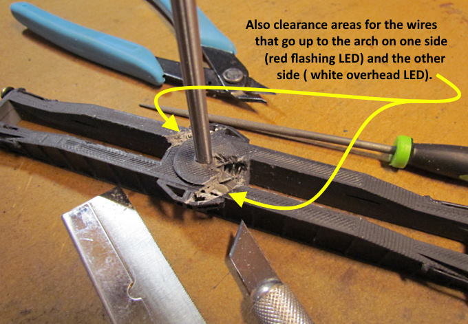
I could go back and edit the bridge file so that it has the cutouts above and below and one wouldn't have to do this. But it just takes a minute to do and I have my bridge done so you guys are going to have to do a little work like I did.
The clearancing above doesn't need to be much as the wires to the arch are very small.
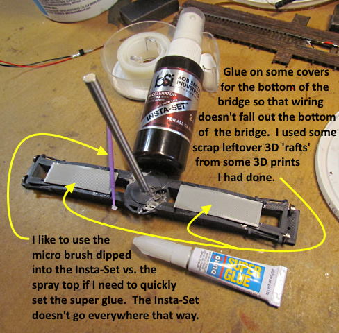
You can make the cover pieces shown above out of about anything. I didn't add print files for them. I print some items, like wire clamps, on a 'raft' in Cura. I keep the 'rafts' and that is what I cut and glued onto the bridge above.
.
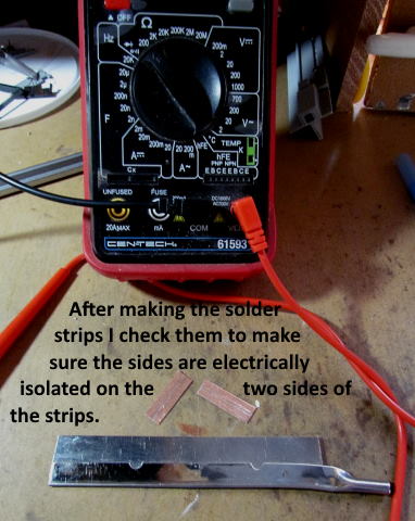
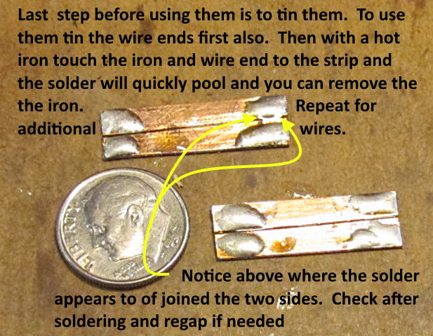
Use a VOM to make sure the two sides of the solder pad are isolated electrically from each other.
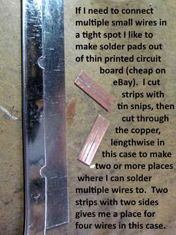
I make other solder pads that can be used on a number of different projects as shown ( HERE ).
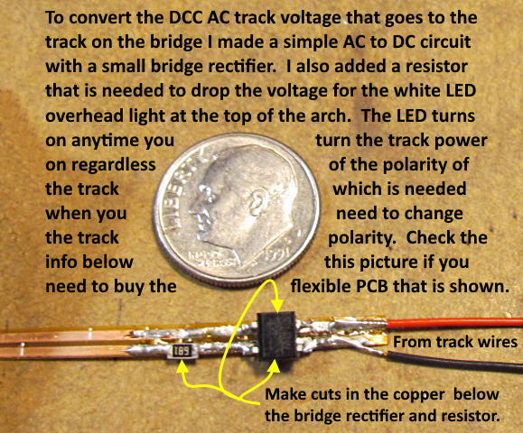
You can find small bridge rectifiers on Digi-Key, eBay and other sources for a couple dollars.
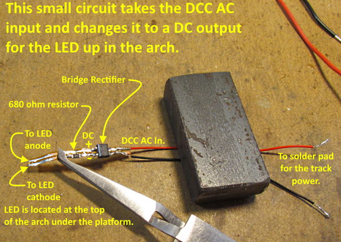
It is pretty easy to solder the components to the flexible PCB strip. Make the needed cuts in the copper that will be under the bridge rectifier (both traces) and the resistor. Next tin the foil next to the the cuts. Place the component on the tinned area one side at a time and touch the tinned area and component just long enough with a hot iron that the solder flows and the component drops into the liquid solder. Use a hot iron so that this happens quickly.
I had a friend in Denmark get the strips for me from a firm in Germany and ship them to me as the German firm wouldn't ship to the U.S. (Thanks Jens). Since then I found a supplier that will ship. I just ordered some (late may 2012) and haven't received them yet but don't expect a problem. I'll post back here if it ends up being a problem say in late June or early July (2021) as they aren't suppose to arrive until mid June.
These 2 conductor strips work very well in decoder installs as they are so thin you can run them places where even thin wiring can be a problem. They make adding LED's in some places a breeze as you can solder a SMD 1208 or smaller LED across the two conductors and if needed add a resistor as shown above to one of the conductors at the LED or some place before it. I could of used short pieces of them glued to something as the solder pads in the bridge to replace the ones I made for printed circuit board. They make nice short or long solder pads in decoder installs. Check out the install that Jen's did where I was introduced to them by his nice write-up ( HERE ) where he installed a decoder in a Kato FEF-3.
Here are two links to the place I recently found the flexible 2 conductor strips where they will ship to the U.S.. ( HERE ) and ( HERE ).
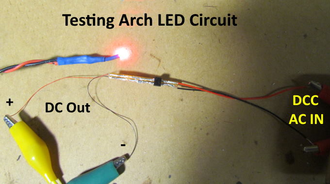
If needed you can use something like the 'clamping' tweezers shown above as a heat sink on a component while soldering.
Checking parts out before installing/soldering into the bridge is a good idea. Above I checked out the AC to DC strip out using alligator clip leads from a section of DCC powered track to the strip and from the strip to a test LED I use.
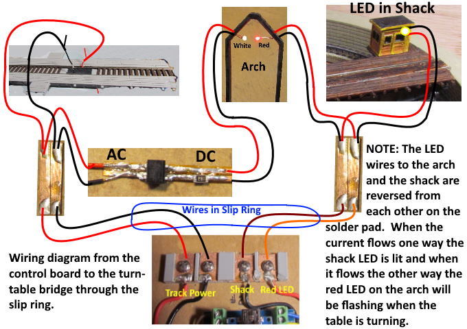
Above is a wiring schematic of the wiring to the bridge, the slip ring under it and how the wiring will be done inside the bridge under the decking. Note that the LED wires to the shack and the arch on the right solder pad are opposite from each other. This might seem wrong but you need to do it in this matter and also make sure the wiring from the control panel (orange and brown wires) that go through the slip ring are also connected as shown between the solder pad and the control board (middle bottom above). The red flashing light and the white shack light are controlled using only two wires by reversing the current to the solder pad. Since the LED's are like diodes when the current flows one way one will come on and reversing the current turns the other one on. If I would of bought a slip ring with 6 wires they could have been controlled independently of each other (should of probably done that).
As it is now if the shack light is turned on with the hand controller and you also then rotate the turntable the red flashing light on the arch will have priority and the shack light will go off while the table is turning. When the table stops rotating the shack like will automatically go back on. I look at this being a 'possible prototypical' feature as the shack light then couldn't cause night-blindness for the operator while the turntable is being operated by him.
Next up is Part 3 of wiring the table.
You can find all the turntable files on my thingiverse.com account ( HERE ).
=========================================
...........................On..............e.........Next Page If There Is One