.................................. Return to Sumner's Home Page....
Return to N Scale RR Main Menu.................. Return to Trackwork Menu
=========================================
...............Previous Page......................................Next Page If There Is One
=========================================
…..........................................................…--- “Gravity-Switcher” ---
....--- Weight/Gravity Operated 3D Printed Switch Machine ---
.......................--- Pulleys and Line Adjusters ---
=========================================
You can find all the files to 3D print this object and others on my thingiverse.com account ( HERE ).
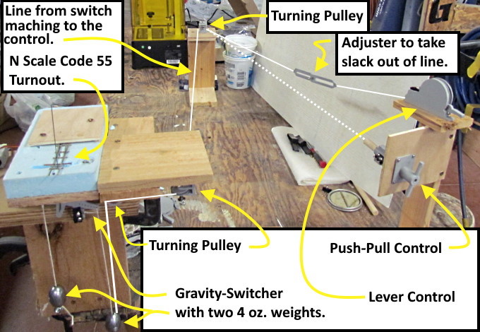
On this page I'll show pulley and line adjuster options for running the control line from the Gravity-Switcher to the control at the edge of the layout.
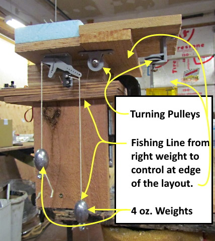
To get from the Gravity-Switcher to the edge of the layout will take a minimum of at least one turning pulley. A lifting line goes to the weight that is on the long arm side of the Gravity-Switcher and the direction of that line needs to change from vertical (pulling the weight up) to horizontal (going to the control on the side of the layout). Above you can see that pulley wheel and bracket almost directly above the weight. If the control at the edge of the layout is close to being in line with that pulley the line can go directly from the pulley to the control you are using.
If the line needs to follow anything but a close to straight course from the pulley above the weight to the layout's edge you will need a way to route the line. One way would be with one or more turning pulleys, one of which is show above to the right of the pulley above the weight.
While testing the Gravity-Switcher and the Push-Pull and Lever Controls I used 3 turning pulleys all shown above. One above the weight and two others to go out and then back to the controls. Next you will find a couple options you can print and use if you so desire.
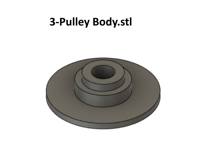
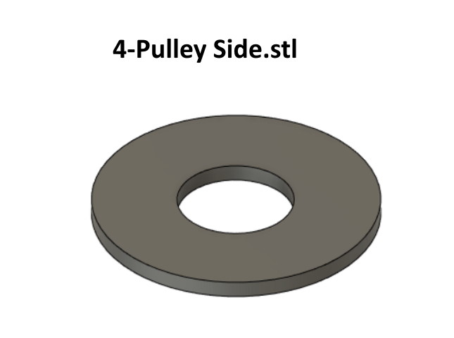
The pulley consists of two parts, the main body shown above and ….
….. a side that you glue onto the main body to complete the pulley wheel.
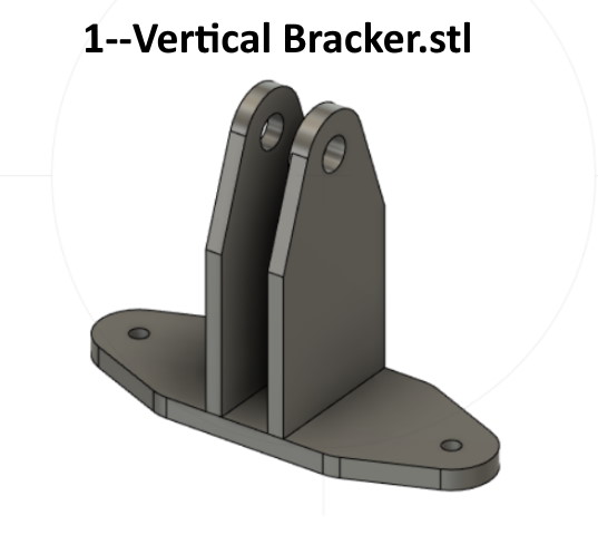
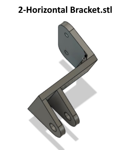
There are two brackets you can print, either of which might work in the same or different situations. I used the one above for the pulley above the weight.
I then used two brackets like above for turning pulleys. Normally these would be mounted under the layout vs. how I mounted them for testing.
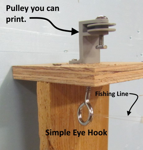
I also tested a simple 'eye hook', as shown above, as an alternative to a turning pulley and it worked fine. If it worked in this test where the line comes back on itself almost 180 degrees I feel it could work easily on lesser angles and you could even use a number of them to get from one location to another. I would use one that is a little more expensive like shown above that is larger and smoother for less friction on the line.
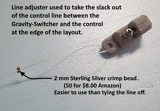
You need to attach the control line ( I use mono-filament fishing line ) to the weight you are lifting and also to whatever you are using to control the Gravity-Switcher at the edge of the layout. I found the easiest way to do this was to connect one line to the weight and another to the control and connect them and take the slack out with one of the following parts that can be printed.
NOTE: You only need to lift the weight enough to put slack in the line that holds it and then the other weight will throw the turnout. You have quite a bit of leeway in how accurate you are in taking 'all' the slack out of the control line. In fact you don't want that line taught. Both of the controls I've put the prints up for have more resulting line travel than needed so leave a little slack in the line and you will be fine.
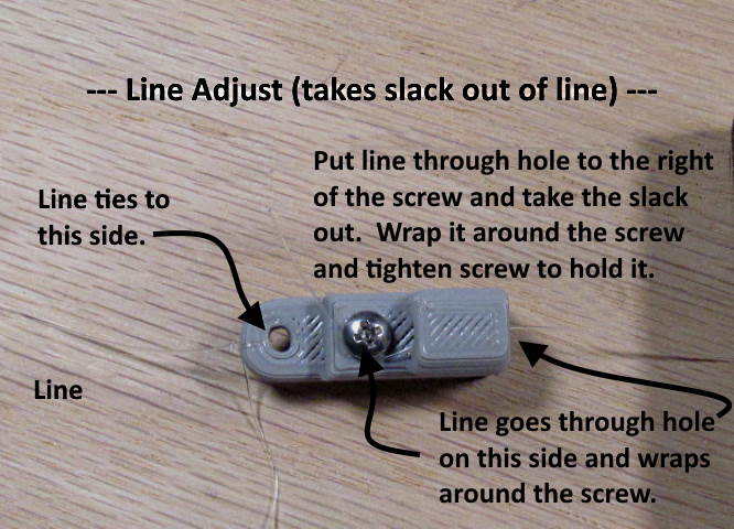
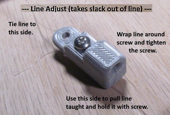
The part above is quite a bit smaller than the photo suggests. Having two lines that you want to connect and also take the slack out of you tie one line to the left side. Then thread the other line into the hole in the adjuster's right side. Pull the line to the point where you have most of the slack out and wrap the line around the screw. Tighten the #2 screw down and you are done. Pretty simple and this is probably the method I'll use the most.
Above you can see the hole that you thread the second line through opposite the end where the other line is tied to.
I also came up with a second method (see below) to take the slack out of the line and will post the parts but I feel the method above will take far less time to print and work as well or better than the next method.
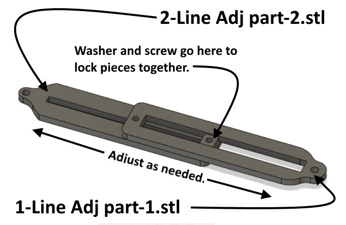
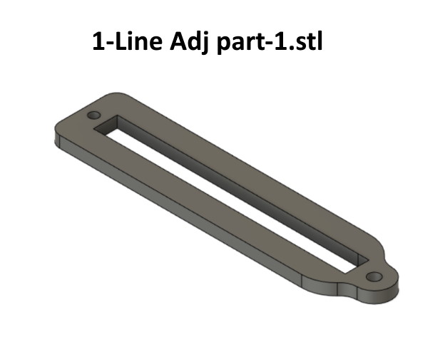
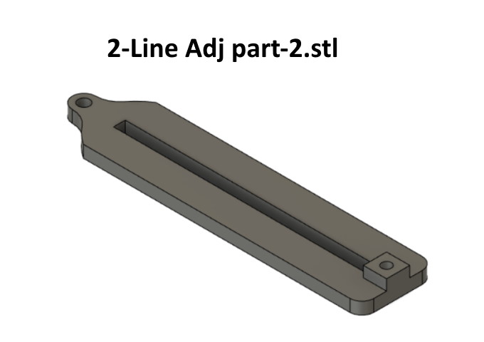
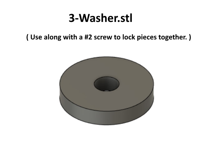
This method consists of two parts that slide on each other. Tie one line to one part and the other line to the second part and put them together hold them in place with a screw and washer in the hole shown above. Slide them together to take most of the slack out of the line and tighten the screw to hole them in place.
.
.
I'm sure others will come up with different ways to run the control line and take the slack out of it. I still need to try simple 'eye hooks' to route the cable. If the route isn't to complicated I'll bet they would work instead of the pulleys.
With the Push-Pull control it is pretty easy to take the slack out right at the control handle. The Lever Control almost necessitates starting with two lines and connecting them although you might be able to run the line all the way from the control to the weight and tie it off and take the slack out at the same time.
I found that using small crimp beads was faster dealing with the line ends vs. tying the line to the adjuster. You can see them in the video link ( HERE ) and in the picture above. I found mine on Amazon using ( Cousin 2mm Sterling Silver Crimp Bead – https://www.amazon.com/gp/product/B00114OPIM/ref=ppx_yo_dt_b_search_asin_title?ie=UTF8&psc=1 ) as a search there.
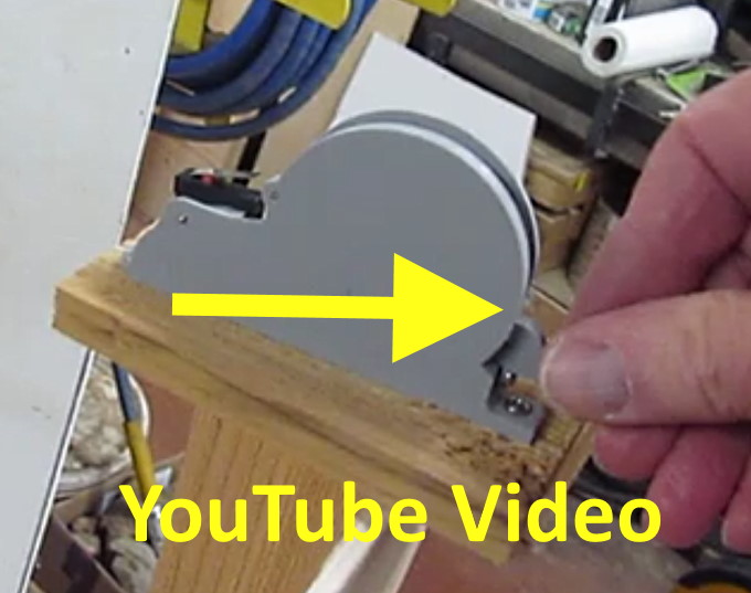
For a video that shows the pulleys and line adjuster on a test of the Gravity-Switcher using the lever controls go ( HERE ) or click on the picture above.
You can find the files to print the items on this page only ( HERE ).
You can find all the files to 3D print this object and others on my thingiverse.com account ( HERE ).
=========================================
...........................On..............e.........Next Page If There Is One