.................................. Return to Sumner's Home Page....
Return to N Scale RR Main Menu... Return to Trackwork Menu
=========================================
...............Previous Page.............................Next Page If There Is One
=========================================
….......--- Installing a Gravity-Switcher ---
=========================================
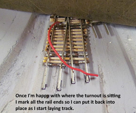
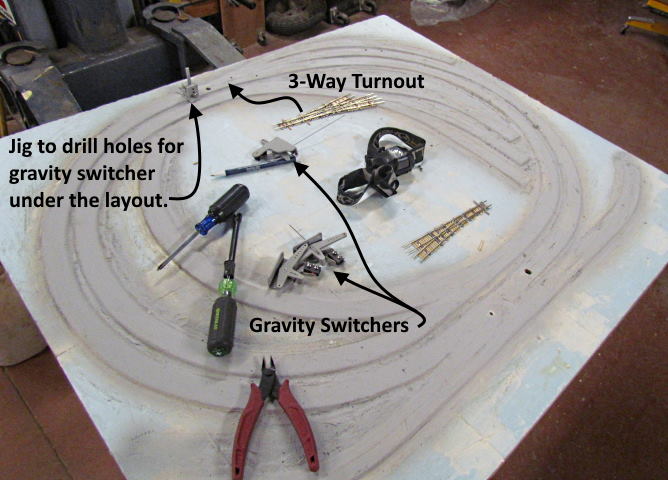
Next I'll show setting a hand-laid 3-way turnout in place that will use one of my 'Gravity Switchers' to control it.
.
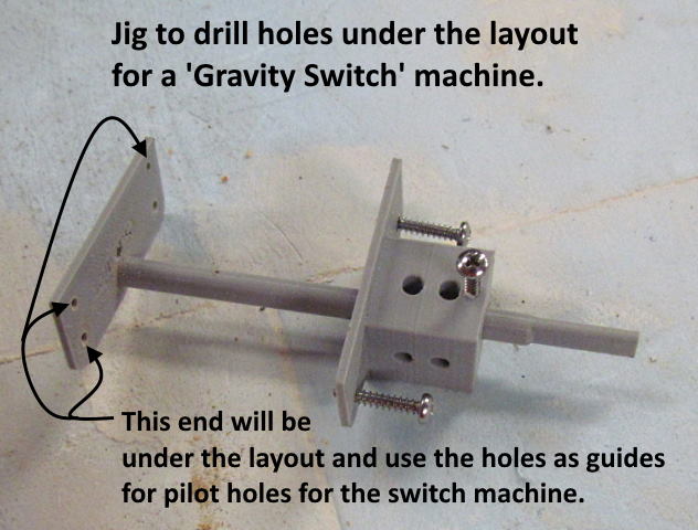
The fixture shown above which you can print really simplifies installing the 'Gravity Switcher'.
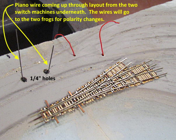
Drill a 1/4” hole where you want the piano wire going to the throwbar located. The wire will end up being in the center of this hole. With the hole drilled put the part of the fixture with the long column up through the hole and hold it in place with the square looking fixture shown above.
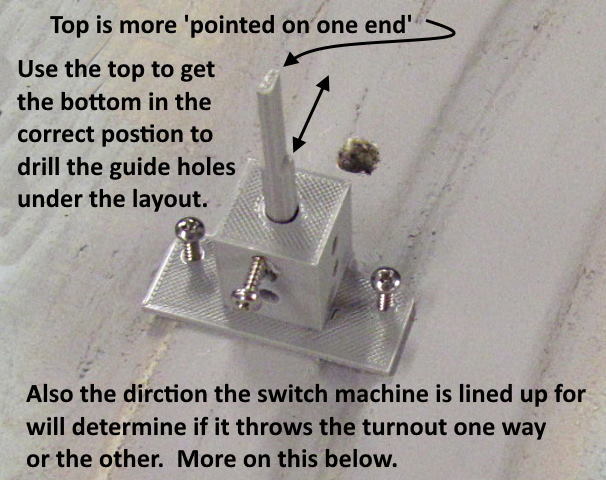
At this point it is important for you to of decide which way you want the 'Gravity Switcher' facing under the layout. Will it face back down the track to the bottom or face upwards to the direction of the track at the top. To help you the top of the column is shape kind of like a wedge. You want the pointed part of that wedge pointed in one direction or the other up or down the track. This will locate the switch machine at 90 degrees to the track as it needs to be. I'll try and describe more about how to determine which direction you want the machine pointed in further down this page. Once you actually do one it will become quite clear I believe.
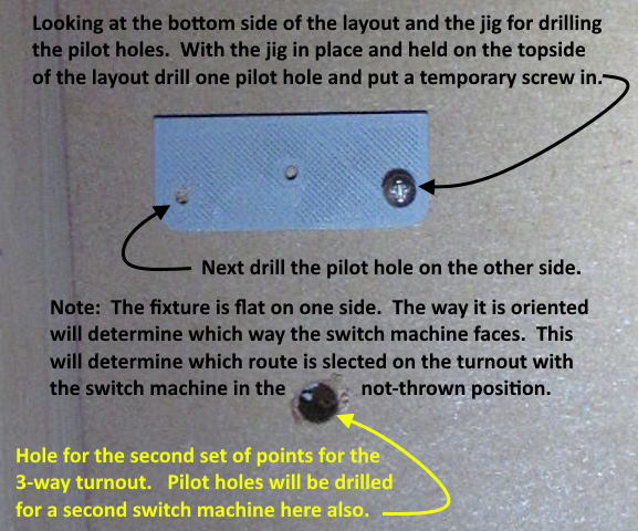
Above we are looking at the fixture under the layout and the shape of it corresponds to the the shape of the mounting surface of the switch machine to further let you know which direction it will be mounted once it is screwed to the underside of the layout.
You will only be under the layout to drill the two pilot holes as shown above and then when you remove the fixture and screw the switch machine to the under side of the layout using the two pilot holes. Using the fixture the machine should be mounted the first time and without needing a helper to help you. Getting older this was very important to me.
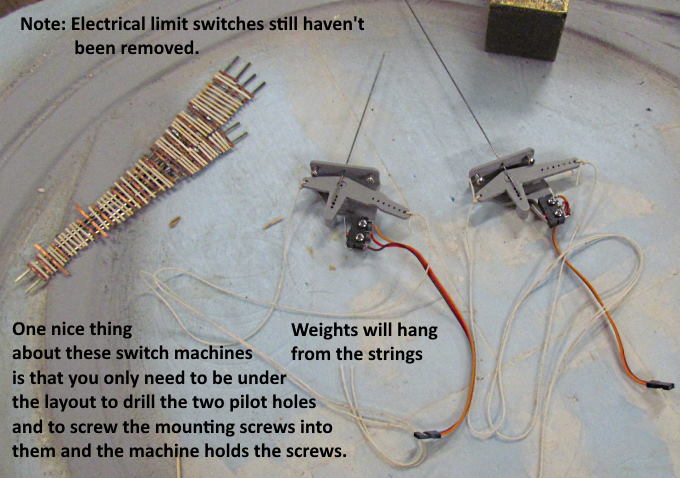
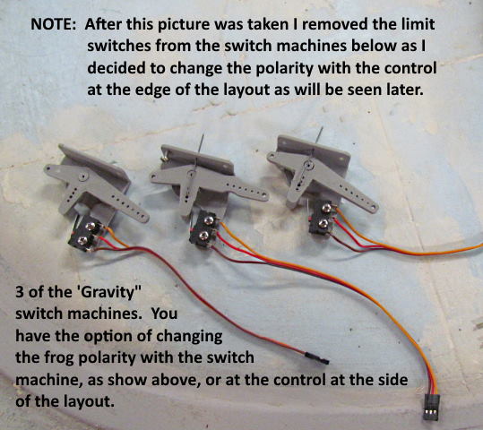
Above we see two switch machines ready to be mounted under the layout. Note that the mounting screws can be screwed into the switch machine which helps as you don't need to get them in place by themselves. Screw them in until they stick out slightly. With the machine under the layout put the piano wire up through the 1/4” hole and push the machine up against the bottom of the layout. You should be able to tell when the screws are in the pilot holes and at that point finish screwing the screws into the bottom of the layout. You shouldn't have to be under the layout very long at all.
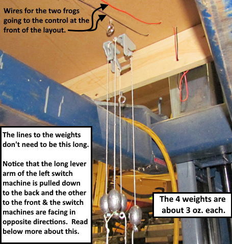
Above one can see that I've attached some strings to both sides of the lever arm assembly. Once the machine is mounted I'll attach the control weights to those springs. Also above you see that I have limit switches attached to the machine at this point. They can change the frog polarity if you use them. If you use them on the machine 4 oz weights seem best. If you use limit switches that are located on the turnout control at the edge of the layout you can go with 3 oz weights. I decide to go that route so removed the limit switches after taking the picture above.
Above the weights have been tied to the lines and the limit switches have been removed. To see more about the 'Gravity Switcher' and how it works and so forth go ( HERE ).
If your control at the edge of the layout hasn't been thrown the switch machine will be controlled by the weight that is on the side of the lever assembly with the longer arm (twice as long as the other side). Since the weights are close to equal weight the weight on the side with the longer arm has twice as much leverage so the machine is thrown to that side until that weight is lifted.
I want my machines to align the turnout to the main route/track when not thrown. In the case of the 3-way shown here you have the straight through route which is my 'main route' in this case. Since the divergent routes go off in opposite directions from the main straight through routes the switch machines are oriented opposite to each other under the layout. When drilling the pilot holes for the machine under the table keep this in mind so that the machine is facing the right way under the table.
You can't just turn the machine around and use the same holes. You could turn it around and drill new holes or you could use a machine with the long lever arm on the opposite side. This gives you two methods of achieving the same throw direction. Above I could of used one of the machines with the arm on the other side and had them facing the same way. If there is an obstruction under the table near where the machine will sit being able to turn it around or go to a machine with the lever arm on the opposite side might help clear the obstruction.
.
.
.
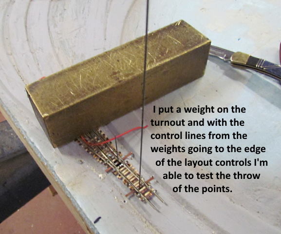
Next up is connecting the 'Gravity Switcher' to one of the control options at the side of the layout. In practice I did this after some of the track to the turnout was down but it might be better to show it now since it would finish out installing the turnout.
=========================================
...........................On..............e.........Next Page If There Is One