.................................. Return to Sumner's Home Page....
Return to N Scale RR Main Menu........ Return to Decoder Install Menu
=========================================
..............Previous Page..............................Next Page If There Is One
=========================================
............--- Digitrax DZ126T Decoder In a N Scale ---
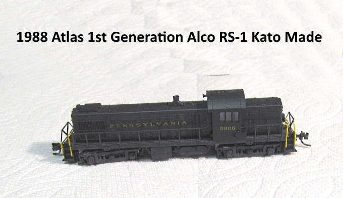
......--- 1st Generation Atlas RS-1 (1988 Kato made) ---
=========================================
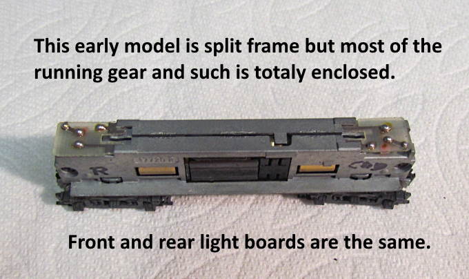
This is a decoder install in the first generation N scale Atlas RS-1 that was made by Kato. I'll put a Digitrax DZ126T decoder in the loco. I bought mine for around $25 from Litchfield Station in Phoenix in 2020. They are good people to deal with and most of the time the freight is only $4.00.
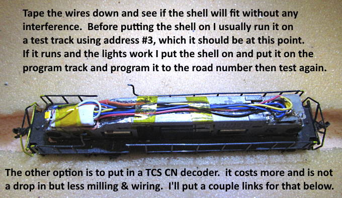
A somewhat easier install can be undertaken by using a TCS CN decoder that inserts where the light boards normally are. It costs about half again as much but there is less milling to be done and less wiring needed. If you go that route look at this link ( HERE ) as I think it pretty much eliminates much of the milling as the light boards are reversed in position. This will require you to change the normal direction of travel when you program the loco depending if you want the cab end to run first or not.
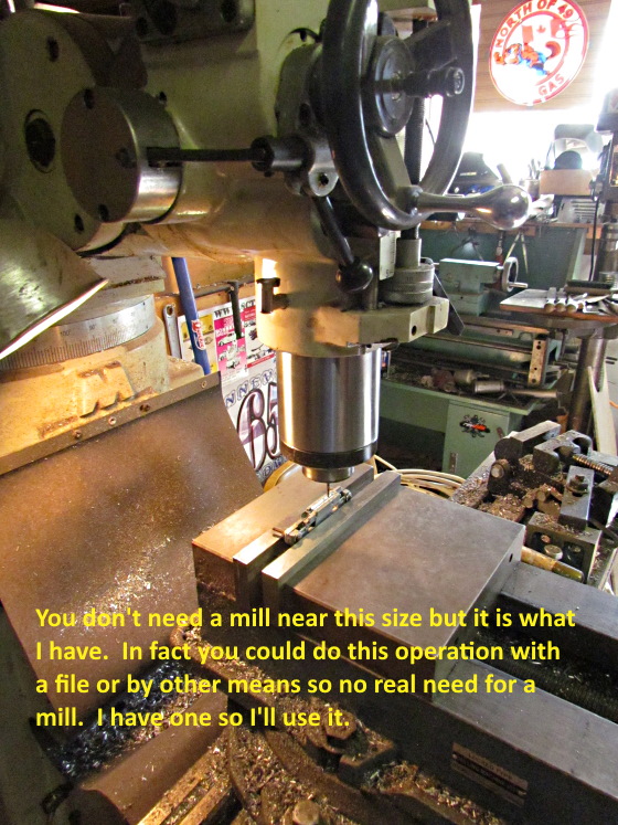
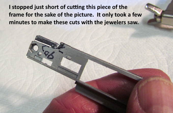
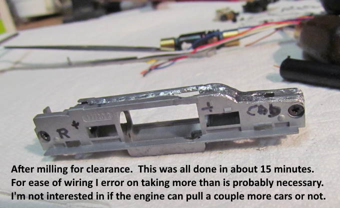
There is going to be a fair amount of cutting/milling of the frame using this decoder but I wouldn't let that put you off as it can be done with tools you might all ready have at hand and it took me less than 45 minutes to do that part of the install.
I picked this loco up off of Ebay for $36.00 and it ran well in DC mode. With the decoder I'll have about $60 in it. Not bad for a nice running DCC loco. I want to strip it and paint it UP as that is what I run.
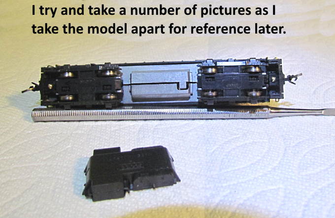
I try and remember to take pictures as ...
…. I take the loco apart as it doesn’t take long for me to forget things later on.
On the next page I'll document doing a decoder install on the second generation (china made) Atlas RS-1. They are pretty similar except in looks of the frame and the running gear is different.
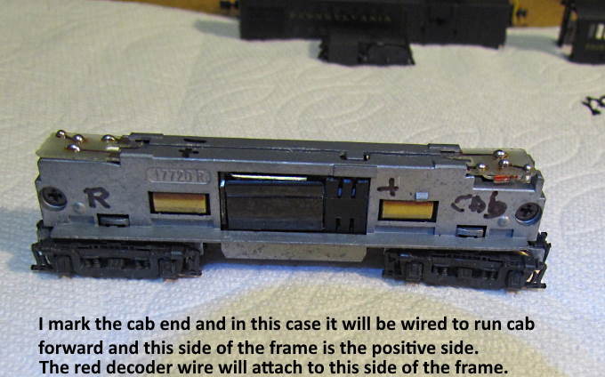
It is easy for me to start forgetting which is the cab end so I mark that.
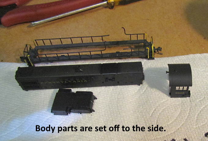
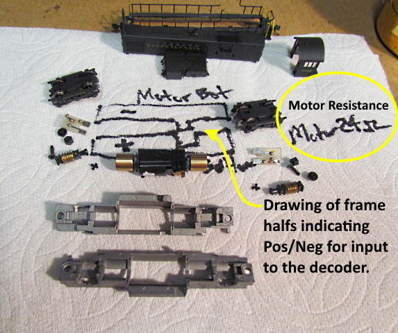
I put the parts on a clean paper towel and also make drawings and/or notes to help along the way.
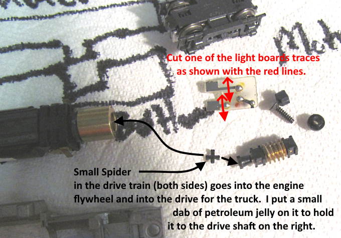
The first generation of this loco has these really small spiders (like U-joints) that go inside the flywheel and attach to the drive to the track gears. I worried about getting them back together at the end but found if I put a dab of petroleum jelly on them they would stick to the drive shaft on the right and you could then slide them into the flywheel and index them there. You need a very small touch of the petroleum jelly so don't go overboard.
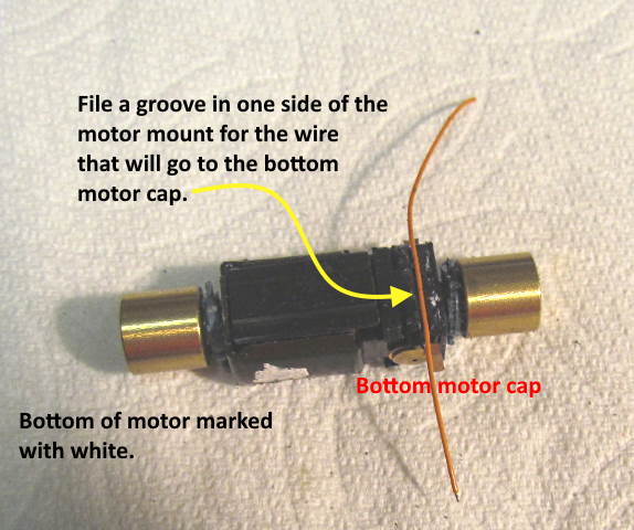
It is easy to put the motor in upside down, especially if the top and bottom look the same (ask how I know). I now try and remember to put a dab of white-out on the bottom.
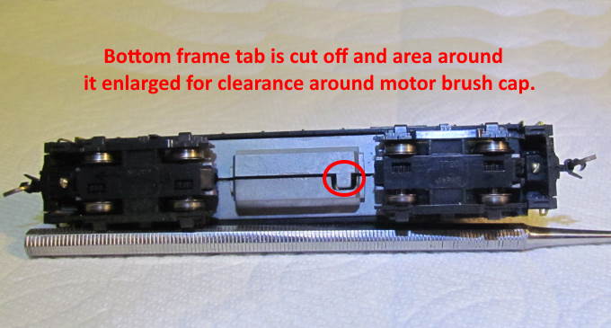
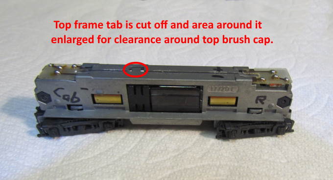
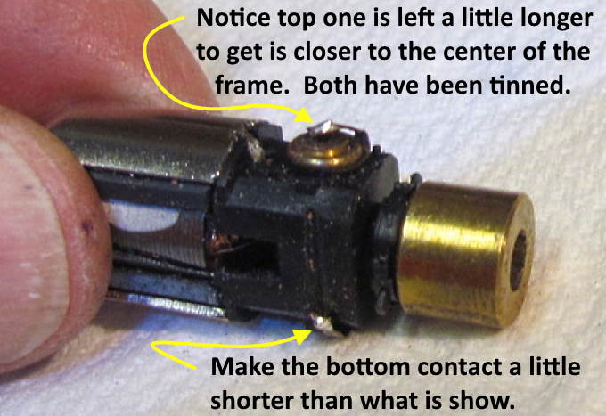
The frame tabs that are over the motor brush caps on the bottom of the loco and ...
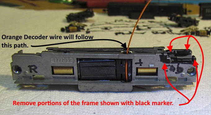
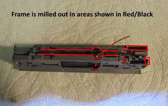
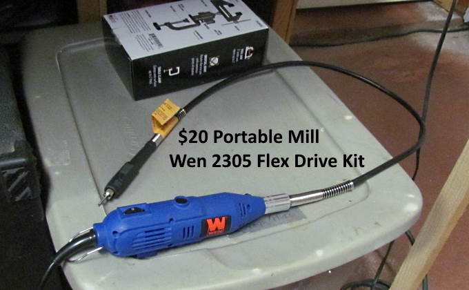
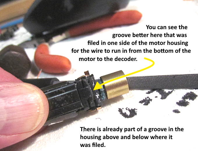
…. on the top need to be removed and the areas enlarged for clearance. You will soldering the orange decoder wire to the bottom of the motor and the gray wire to the top and you don't want any frame coming into contact with the brush cap, solder joint or exposed wire where it is soldered on. I cut the tabs off with my jewelers saw and enlarged the opening with my flex drive rotary tool that you will see below.
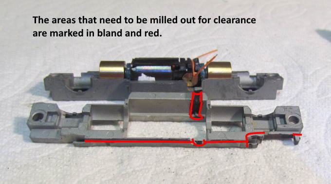
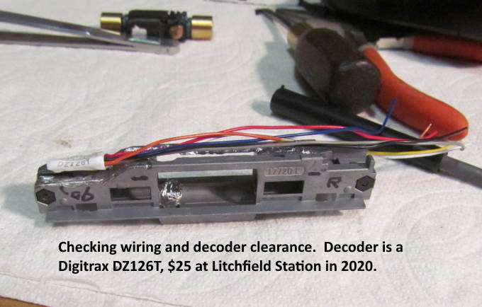
I mark the frame where I want to mill it for wiring and decoder clearance.
In the picture above and the next one the frame tabs by the motor brushes have already been cut off.
.
I have a large mill that I've used to mill frames with but I don't see much need to use it anymore. One has to be very careful with it to not distort the frame and it takes time to setup with it and use it.
I'm now totally happy with the speed and ease that I can mill a frame using a $20 Wen 2305 flex drive rotary tool.
.
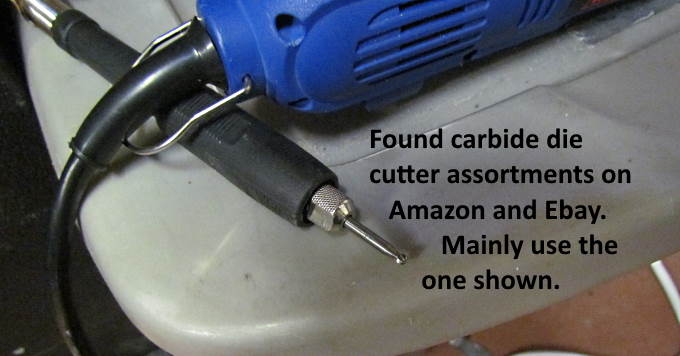
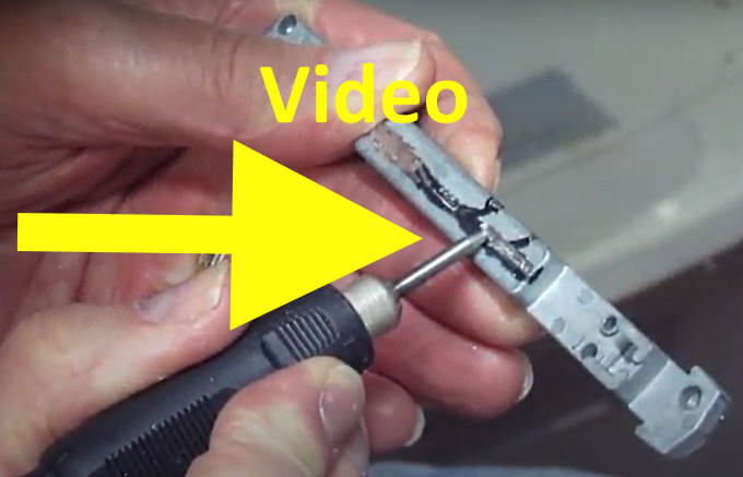
I have a video up using the rotary cutter ( HERE ).
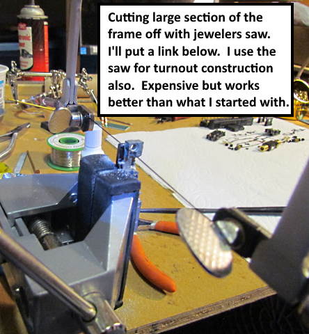
I've also found it is very quick to cut off large pieces of the frame when possible with a jewelers saw that I bought to help in making handlaid turnouts. This is the second saw I bought and about twice the price of the first one but much better as it is easier to get the blade tension right for easy cutting. It is a Megacast German style jewelers saw that I found on Amazon ( HERE ). I highly recommend spending the money on it.
It is quick and easy to use but you need something to hold the piece steady and for that I recommend the Fasmov Swivel 3” Universal Table Vise you can find at different locations such as ( HERE ). I use this vise all the time and have two now. One in each work space that I use which aren't next to each other.
You have a couple different options for power pickup to the decoder and a place for lighting. One is to modify the original lightboard like above and in the following pictures.
The other is to make a small lightboard/power pickup like what you see above and there is more info on it ( HERE ).
.
.
.
.
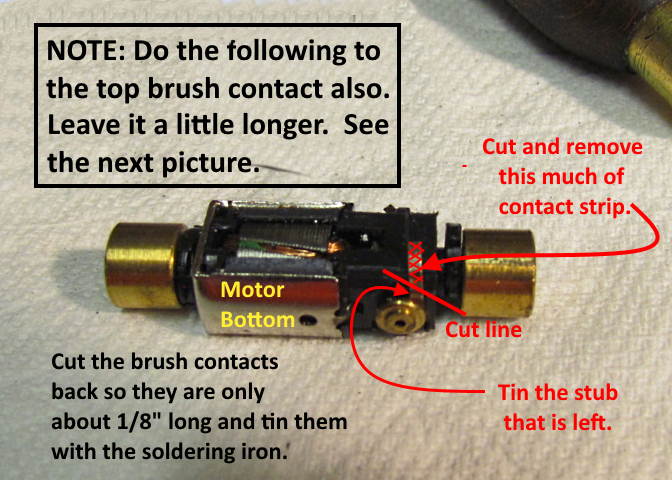
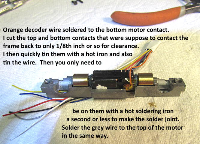
The picture above is from a second generation RS-1 so the motor looks a little different but you need to trim the brush cap contacts back as shown and tin them on the top and bottom of the motor you are working on so they don't contact the frame.
Again the picture above is a second gen. Atlas RS-1 but what you want to do is the same.
.
.
.
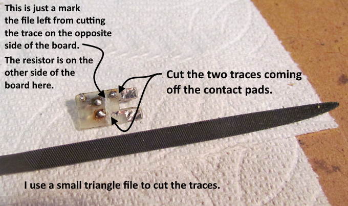
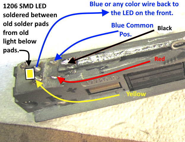
Above one of the original light boards is going to be used for power pickup for the decoder after cutting two of the traces.
I also replaced the incandescent bulb with A LED. If the board happens to have an LED you could keep it or the same with an incandescent bulb if you like it.
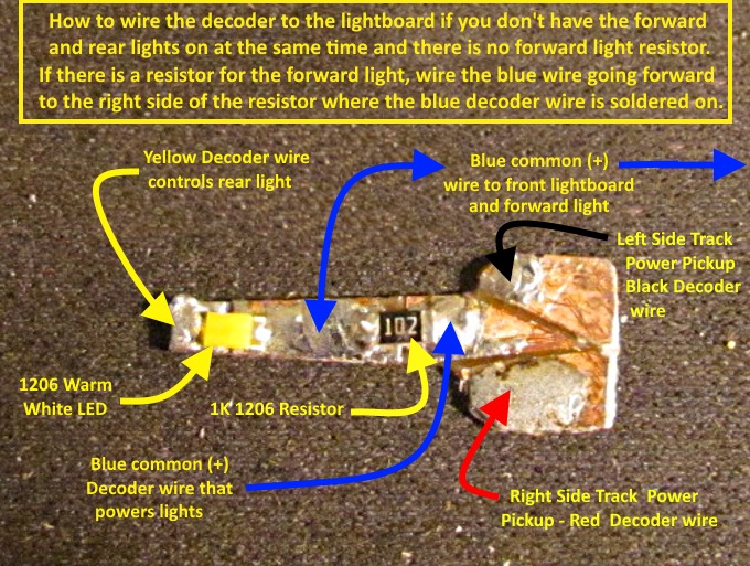
Above you can see where each colored wire goes. The lighter blue wire takes current after the resistor back to what is the forward LED. The one resistor will work for both if they aren't on at the same time (decoder set to change lights with loco direction change). The wire (shown as light blue above) from the solder post to the other LED can be whatever color you want.
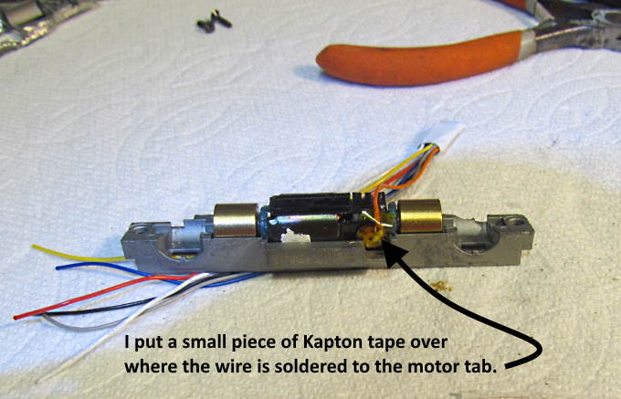
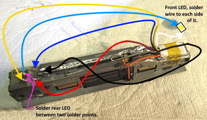
I soldered the light blue wire going to the front 1206 SMD LED to one side of the LED and the white decoder wire to the other side and laid it on top of the decoder and taped it there. The light blue wire carries the positive current after it has gone through the resistor on the lightboard to the forward LED. The white wire goes to the decoder and grounds the circuit when the decoder turns on that function. The LED and soldered on wires should not touch the frame anywhere or you will 'smoke' the decoder.
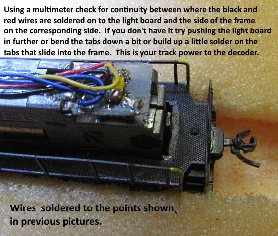
With a multimeter check several things before putting the loco on the track.
1. There should be no continuity between the frame half’s.
2. If you check between the motor caps (orange and gray wires) there should be no continuity between them and either frame half. Between the two measuring through the motor you should see a ohm reading. With this motor it was about 24 ohms.
3. If you touch the red or black wire where it is soldered to the lightboard and check continuity between it and the frame half on that side you should see continuity. I check from there down to each wheel on the same side of the frame and that tells if the continuity from the rail up to the frame and on to the decoder is good.
If any of the above don't check out fix it before putting the loco on a powered track.
Above and on the left side you can see the front LED with wires soldered to each side of it taped to the top of the decoder.
That concludes the install and I found the loco to run very well with this decoder but I don't have a lot of experience as to what 'very well' is at this point ;-).
Info on installing a TCS CN decoder ( HERE )
=========================================
...........................On..............e.........Next Page If There Is One