.................................. Return to Sumner's Home Page....
Return to N Scale RR Main Menu........ Return to Decoder Install Menu
=========================================
..............Previous Page..............................Next Page If There Is One
=========================================
.--- Making a Smaller Lightboard for More Space ---
=========================================
NOTE: Here are a couple links to Printed Circuit Boards that might help for finding materials to do this mod. I bought the .021 PCB noted below from the seller ( HERE ) but as I write this he doesn't have any. I've also bought PCB for my PCB ties I use making turnouts from the seller ( HERE ). He has a number of different options in his store ( HERE ). At the moment no .021 but some that actually might be better as I had to file one side of the .021 a bit to make it fit. As I write this he has some .020 single sided that might work great since then you don't need to make the isolation cuts in one side. He also lists some .016 that is double sided. I'd probably get that and if it is a little loose solder a small pad on one side to make it a tight fit where it slides into the loco's pickup slots in the frame.
=========================================
During my first 'wired' decoder install where I had to mill a pocket for the Digitrax DZ126T decoder I didn't like how much space the stock lightboard took up above where I was going to install the decoder. I felt if I could replace it with something smaller I'd have more space for the decoder and the wiring going to and from the decoder.
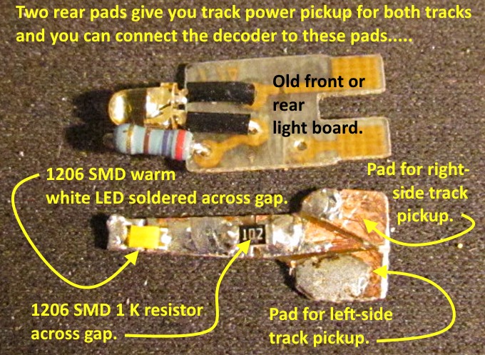
I took a narrow strip of printed circuit board (PCB) I had cut from a larger sheet I'd gotten off of eBay and made two cuts across it with a file so what remained were 3 sections of PCB that were electrically isolated from each other. I then soldered a 1K SMD (surface mount device) resistor across one of the cuts and a SMD LED across the other. I soldered a positive 12 volt wire to the end with the resistor and what would become the negative lead to the other end of the PCB. Current flows through the resistor to the LED and then back to the source. (note: you do have to solder the LED on with the anode end towards the resistor so that the current will flow through it and light it.)
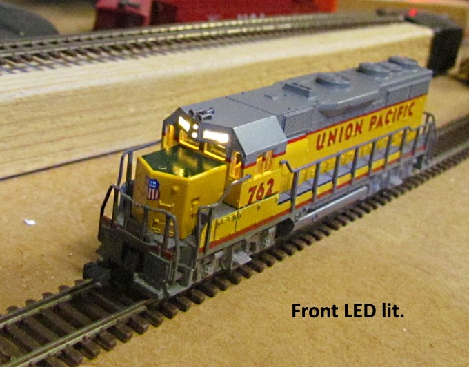
This worked well and would take up less room than the stock lightboard shown above it. I'd still need to wire this to the decoder and support it in some manner and I also would still need to get track power (negative and positive) to the decoder.
I felt that one could make a smaller board than the stock light board that would accomplish all of this. The problem came down to finding the right thickness PCB board that would slide into the frame half’s where the lightboard normally resides. I measured the thickness of the lightboard and found it to be about .019 thousands thick and noticed there was only copper on one side. I found some .021 PCB board on eBay and ordered it. I cut it out like in the picture above with tin snips and then filed most of the copper on the bottom side to the point where it would slide into the frame where the lightboard had before.
I made isolation cuts in both sides of the top so that there wouldn't be a short between the frame half's. I also made two cuts that the resistor and LED would span.
IMPORTANT: On the bottom side of the printed circuit board you need to also make cuts in the board. The cuts have to separate one side of the PCB from the other to avoid the short that would take place between the frame half's as they are carrying the track voltage from each rail. You don't need cuts below where the resistor and LED sit on the top side.
With the PCB cut like above you end up with a place on both sides where you pickup the track power from and a place for the resistor and LED as shown in the next picture.
Above you can see the resistor and LED soldered to the PCB. I also tinned the areas where the decoder will pickup track power.
I tin the areas where the LED and resistor are soldered to the board and also tin the ends of the LED and resistor using GC Electronics 10-4202 liquid flux. Next hold the LED or resistor flat on the board over the isolation cut in the board with curved tweezers . Melt a point of solder on the end of the solder iron and just touch it to the end of the LED/resistor and board at the same time for a second and that will solder one end on. Repeat for the other end. Don't use a lot of heat or for too long or you might damage the LED or resistor.
To tin the ends of the LED/resistor I use the 'LED/Wire Holding tool' from ngineering.com that you will see at the bottom of this page. Also their 12 watt iron is great for all of this work.
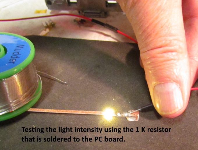
You can adjust the light's intensity by the resistance value of the resistor. I chose 1 K for now but it would be easy later to un-solder the resistor and re-solder a new one onto the PCB of a different value.
Above I'm test fitting the new lightboard above the pocket that had been milled in the frame for the decoder. You can see the Digitrax DZ126T decoder below it waiting to be wired in.
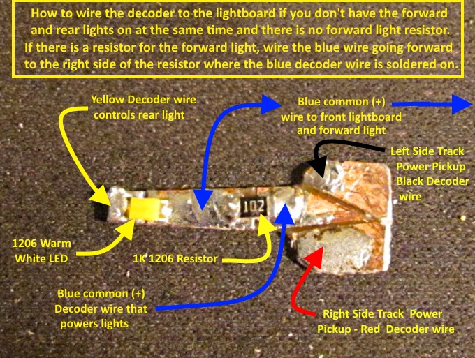
The picture above shows how most of the decoder wires connect to the new lightboard. The solder pads on it make it easy to connect these wires.
If you have a resistor for the LED on the front lightboard, connect the blue wire going to it on the right side of the resistor at the same place you soldered the blue wire from the decoder, instead of between the resistor and the LED.
This lightboard gives you nice easy to use solder pads for most of the decoder wires. Only the two motor wires (orange & gray) and the white control wire to the forward light, along with any other special function wires, go some place else.
I made a second light board for the front of the N-scale GP-35. You could cut traces on the old one and use it but you can make these in under 15 minutes or so. I didn't install a resistor on the front one as I would be running power to it from the rear lightboard taking the power just after the resistor on that board. This will work as the decoder will only be running one light at a time. If you wanted them both lit at the same time I'd install resistors on both boards to make sure you stayed in the wattage.
The SMD resistors I used were 1206's which is also the size of the LED's. You could use even smaller ones but these were small enough for me to work with considering my age and eyes and hands. ngineering.com is a great source for tools and info on soldering and using SMD resistors and LED's. I bought their tools that can hold the SMD's for soldering and also their 12 watt soldering iron along with a number of other items. Great site and great products.
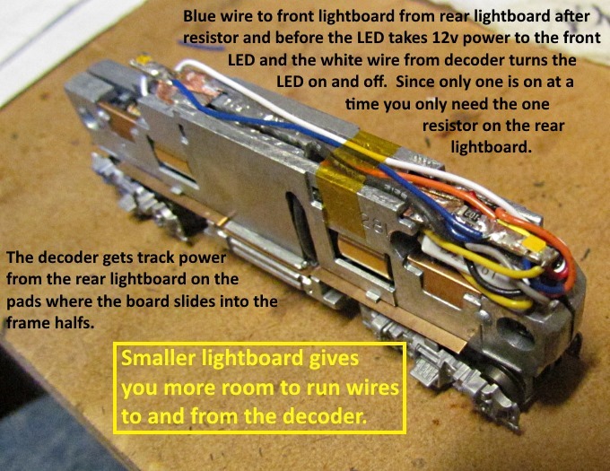
In the picture above you can see how the smaller lightboard opens up room on both sides to run the wiring to and from the decoder. Also it is hard to see but the decoder wires that provide track power to the decoder ares soldered to the pads on both sides of the new lightboard just aft of where it slides into the frame.
You can also see where the blue power wire is soldered to the rear lightboard between the resistor and the LED. It takes power to the front lightboard and the white wire goes to the forward end of the front lightboard and the decoder uses it to turn that light on or off. On the rear lightboard the blue wire from the decoder is soldered ahead of the resistor and the yellow control wire is soldered to the end where the LED is and controls if it is on or off.
.
I'm happy with the results and also the fact that my first 'wired' decoder install was a success. It will be documented elsewhere on the site.
Above is one of the tools from ngineering.com that really helps if you are soldering a wire to one of these small LED's.
You can find the SMD resistors and LED's on Ebay and other sites for very little money.
========== Yet Another Option ==========
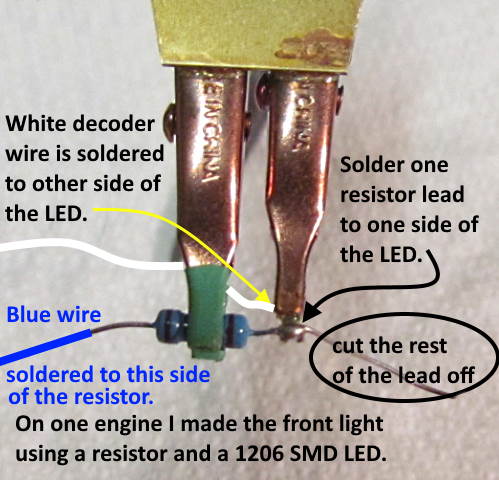
Following is another option using a standard resistor and a SMD (surface mount device) LED.
Take a resistor of the value you want for the intensity you like and solder the anode (+) side of the SMD LED to it as shown above. Cut the rest of the resistors lead off that is past the solder joint with the LED. Solder the white or yellow decoder wire to the other side of the LED (cathode (-) side). White wire if you are working with the front light and yellow if it is the back light. It could also be some other function wire if you are working with more than a two function decoder.
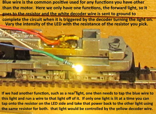
The blue, common positive, decoder wire is soldered to the other side of the resistor. If you have another light or function you need to splice into the blue wire either ahead of the resistor or after it before the LED and take positive current to that function. If you need full decoder voltage to the other function splice in (solder wire) ahead of the resistor.
In cases where I have a forward and rear light that are only on one at a time I splice (solder) in just after the resistor and before the LED. Then take that wire to the other light or LED. It will be the decoder's blue supply voltage but reduced by the resistance of the resistor. Then connect either the white or yellow decoder wire to the other side of the LED. Using this method the one resistor will handle both lights, one at a time, as they are turned off and on to match the loco's direction. This is explained again in the following picture.
.
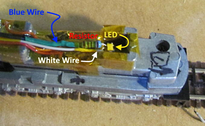
Above we see an example of wiring the light like this in a Con-Cor U50. The complete decoder install is ( HERE ).
=========================================
...........................On..............e.........Next Page If There Is One