.................................. Return to Sumner's Home Page....
Return to N Scale RR Main Menu........ Return to Decoder Install Menu
=========================================
..............Previous Page..............................Next Page If There Is One
=========================================
...........................--- Decoder Tester Part 4 ---
Time to finish the decoder tester.
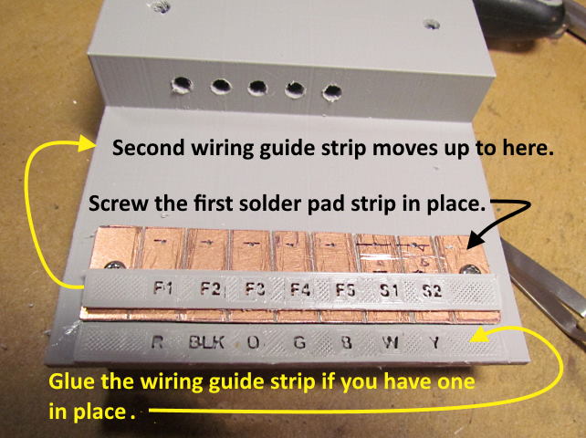
As shown above glue the bottom wiring guide strip to the top.
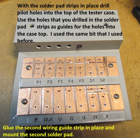
Next temporarily mount the bottom solder pad strip in place above the guide strip. Then glue the second wiring guide strip in place and mount the second solder pad strip in place also.
With the soldering strips in place drill pilot holes where the wires and resistor leads will be. This it the time to also drill the pilot holes in the case for the #4 Screws if you are going to use them for terminal screws. If you aren't sure I'd still drill them now in the case top and also in the printed circuit board if you haven't done so. Again make sure you remove any copper from the other side of the board near any of the holes to avoid any shorts that could take place on that side.
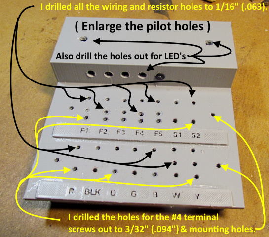
If you used single sided PCB you don't need to worry about the other side and then you could also drill holes for the terminal screws later. I use a 3/32” bit (.094”) for the screw holes. If for some reason you ever stripped the threads out in the case you could glue on some of the feet found ( HERE ) for the screws to thread into.
Pull the solder pad strips off and enlarge the pilot holes some. This will make it easier to insert the wiring from the bottom side in the next steps.
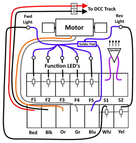
Above is the wiring diagram. I'll take it for granted that it is obvious that the decoder wires are soldered to the bottom of the solder pads or placed under terminal screws there.
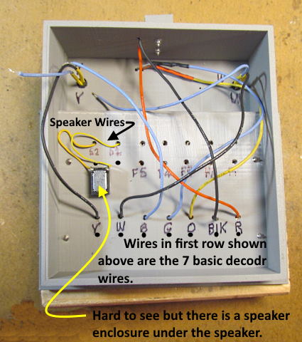
Above is the wiring for the basic 7 decoder wires that you will find on almost any decoder along with wires to the speaker that is glued to the top of a speaker enclosure/baffle. I've gotten some of my speakers and enclosure baffles from Streamlined Backshop and have also been 3D printing some custom height enclosures also.
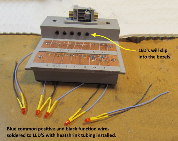
Next make up LED's with wires to use for the 5 functions and the forward and reverse LED's. I used red for the functions and white for forward and yellow for reverse. You can use what you want.
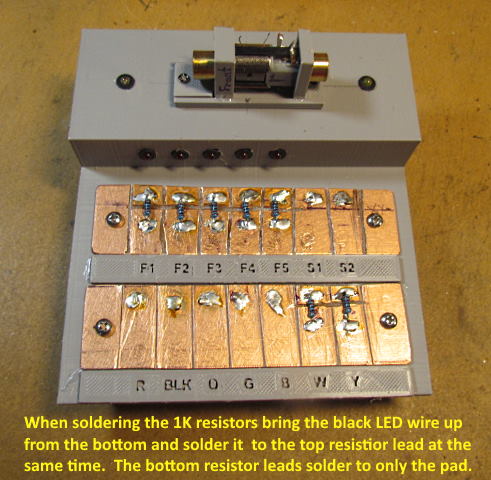
Time to finish the wiring. I inserted the wires for the 5 functions and the forward and reverse lights from the bottom after tinning them and bent them over so they would stay in place. Then inserted the 1K resistors from the top and soldered the resistors and wires from below to the solder pads. There should be an isolation cut under the resistors. You want the wires to the LED's above the cut and soldered to the pad and resistor lead there. Next you can cut the excess resistor leads off inside the case.
The 1K resistors should be fine for red, white and yellow LED's up to 15 or 16 volts.
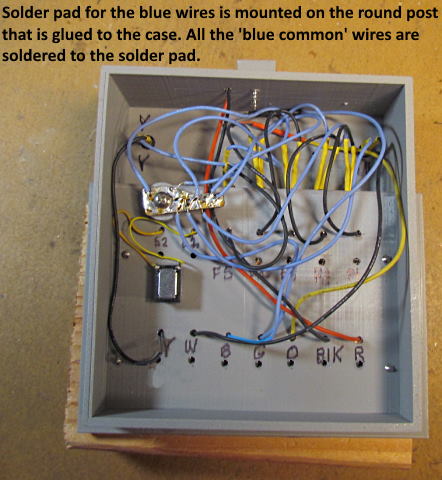
Finish up the wiring to the top solder pad strip functions and speaker pads. I glued a 1/2” diameter post that you can print to the inside of the case and attached a simple PCB solder pad to it with a #4 screw. This made it easy to solder all the common positive blue wires to that go to all the LED's and the blue wire from the pad the decoder attaches to.
NOTE: Most of the wires above are the correct color but I didn't have a gray one long enough to go from the solder pad to the motor so used a blue one for part of that distance. That is why you see a blue wire in the hole marked 'B' and 'G' above. The same with an orange wire for the hole marked 'O'. I had to use a length of yellow wire until I got near the motor.
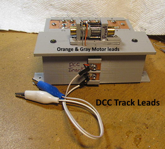
I put a 2 pole solder pad on the back for the wires that go to the track. You can find the solder pad ( HERE ). Of course the wires that clip on to either the program track of the main can clip on in any order since it is DCC.
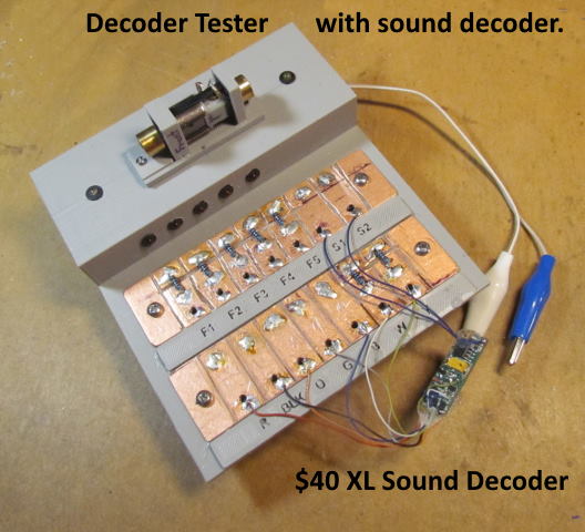
The tester is finished and I'm really glad that I made it. It has already come in handy, especially with the sound decoder I bought. I was able to test it with the speaker that came with it, Then connected to the speaker in the tester and finally I was able to pick a speaker and enclosure/baffle that I liked and that will fit in the GE U28C that the decoder is going in. If I would of started by installing in the U28C I probably would have had to cut the speaker out a couple times before finding the one I wanted. The speaker type and brand and the enclosure/baffle can make a big difference in the final sound. Above or ( HERE ) you can see the decoder tester in use.
Again I'd like to encourage one to make a tester. Wish I would of sooner. Also it doesn't need to be a 3D printed case or be setup exactly like I've done. Lots of options for the case and how you set it up. Take a look a Brad's ( HERE ) and make it your own.
If you have a printer and want to print the parts that I've used you can find them on my thingiverse.com account ( HERE ).
=========================================
...........................On..............e.........Next Page If There Is One