.................................. Return to Sumner's Home Page....
Return to N Scale RR Main Menu........ Return to Decoder Install Menu
=========================================
..............Previous Page..............................Next Page If There Is One
=========================================
...........................--- Decoder Tester Part 5 ---
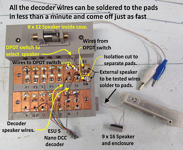
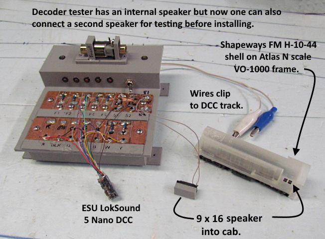
The decoder tester was working well but I started getting a few more sound decoders and found that I'd like to check out the speakers I was going to install before getting them installed and finding out I didn't like them. What happened on my first sound install. I still wanted an internal speaker so came up with modifying the tester by adding a DPDT toggle switch and doing some rewiring using the solder pads I already had on the tester. Now at any time I can switch between the internal tester's speaker or a speaker I want to test that is attached to two of the solder pads.
I was surprised to find out that I think the 9 x 16 speaker above will fit sideways into the FM H-10-44 shell. At least if goes in at this point.
On each pad you will see black holes. I did have screws in the holes and could strip the ends of the decoder wires and put them under the screw heads. I found that it was actually easier and faster to strip the ends, tin them and then quickly solder them to the 'globs' of solder on the solder pads. Quicker to pull them off also with a hot iron. Touch the solder 'glob' and pull the wire off the pad.
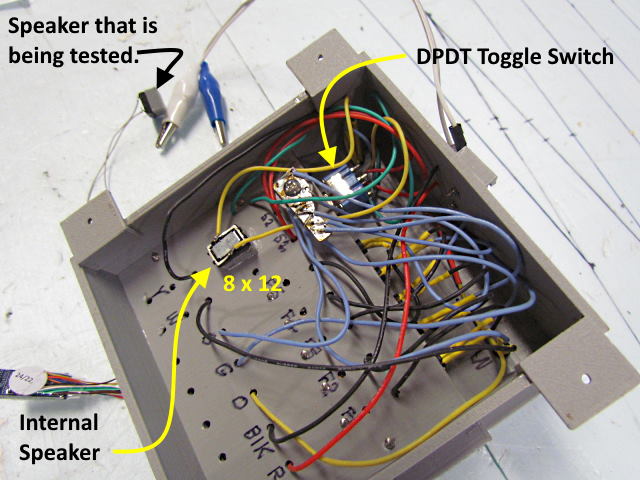
I drilled a .250 hole and mounted the DPDT toggle switch right behind the two solder pads where the speaker wires from the decoder go. Wires from those two pads go to the center posts on the toggle switch. Wires from the outer posts go to the internal speaker and to the two pads that the wires from the speaker being tested go to.
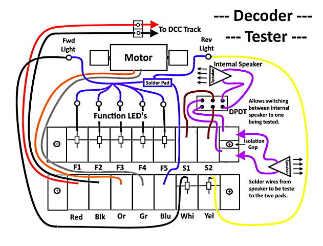
The wiring is pretty straight forward and nothing that would be considered unusual. F1 to F5 solder pads can be used for up to 5 addition decoder function outputs. There are resistors and LED's for each. Connect the extra decoder outputs to the pads and program as needed. If you only have two functions, normally the forward and rear headlights you won't use them only the pads on the first row marked 'Whi' and 'Yel'.
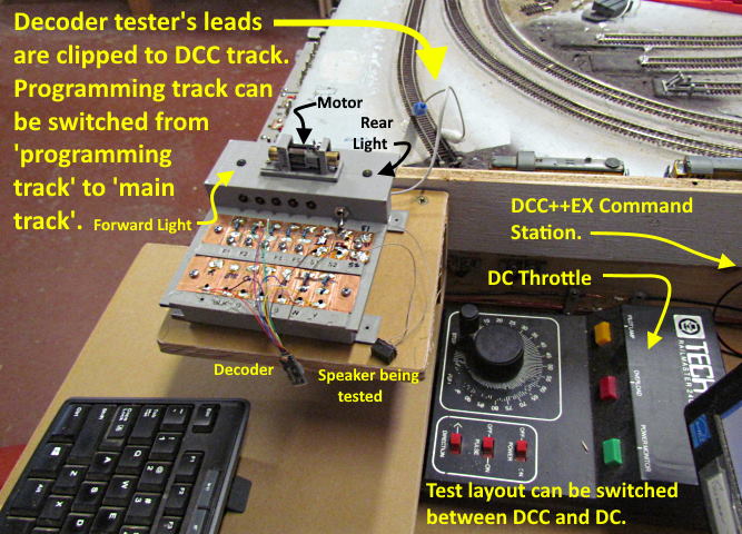
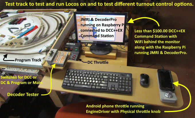
I clip the input leads to the decoder to my program track that can be switched between 'program track' and 'main' with a toggle switch on the front of the test track.
I'm very happy with the combination shown above. Not expensive and very versatile.
The print files for the tester are up on my thingiverse.com account ( HERE ).
=========================================
...........................On..............e.........Next Page If There Is One