.................................. Return to Sumner's Home Page....
Return to N Scale RR Main Menu........ Return to Decoder Install Menu
=========================================
..............Previous Page..............................Next Page If There Is One
=========================================
...........................--- Decoder Tester Part 3 ---
Rereading the previous page I feel some areas need to be addressed before going forward.
I have my tester set up to where I can attach the decoder wires under screw head or by soldering them to the solder pads. You need to decide when making the solder pads if you want to only use the solder attach method or the screw head method or be able to use either.
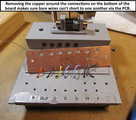
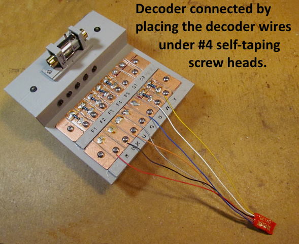
Above I have a decoder attached to the tester by putting the decoder wires under the #4 self-taping screw heads and tightening the screws down. Next ...
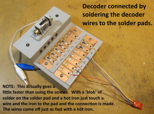
… I have attached the same decoder by soldering the wires to the solder pads. This might seem slower but once you have 'blobs' of solder on the pads you can solder the wires to those 'blobs' very quickly with a hot iron, well under a minute. If you want both options I would move the screws more towards the center of the pads to have more room to solder wires if you take that course. The screws are not shown in the picture above. I normally have them in even if soldering the wires to the pads. I do unscrew them a couple turns so they aren't tight against the pad as they would suck the heat out of the pad when you are soldering to them. That would lengthen the amount of time you would need to have the iron on the pad and the wire you are soldering to it.
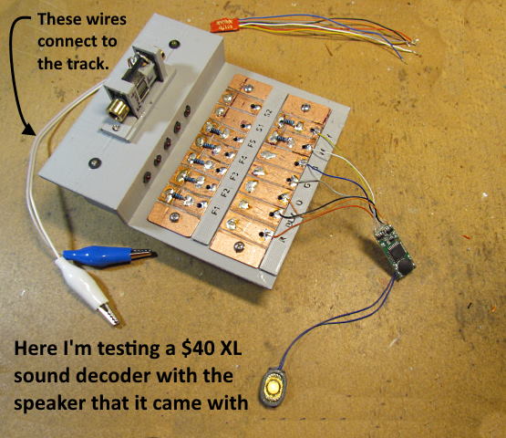
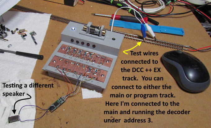
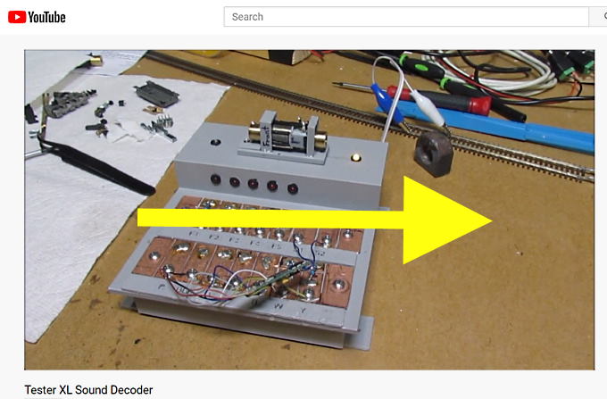
Above I have a XL sound decoder attached to the tester by soldering the decoder wires. I don't have it connected to the solder pads for the internal speaker since I wanted to hear the speaker that came with the decoder. Next I connected it to the track and ran the decoder as address 3 with a JMRI throttle.
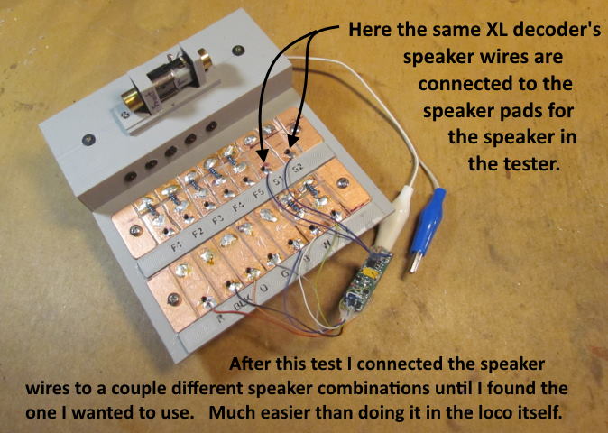
Next I cut the speaker off and wired the same decoder's speaker output to the internal speaker so I could compare the sound and the internal speaker is of a size that I could use in the loco the decoder was being used with so a good comparison.
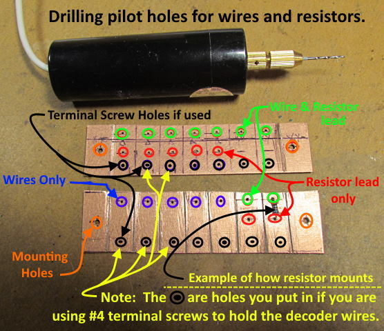
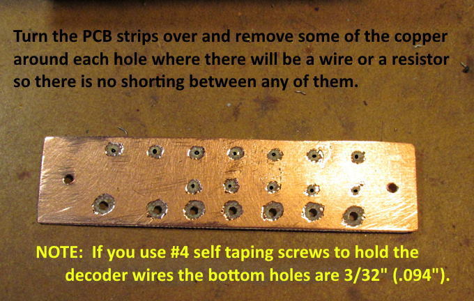
You will need to drill pilot holes in the solder pad strips like above. You will need to put in the 'green', 'red' and 'blue' holes for sure. If you don't want the screw terminal option don't drill the holes that are circled with the black circles. If you do want that option then drill all the holes circled with the black circles. I would move them a little higher (as shown in the picture) to give you more room to also solder on 'blobs' of solder for connecting the decoder with the solder method when you want to use that method.
Once you have the holes drilled if you are using double sided printed circuit board like I was you need to go to the back side and remove some of the copper around each hole. If using the screw terminal method drill those holes out now to the correct size as shown for the #4 screws and remove copper around those also. You don't need to remove copper around the end two mounting holes that are shown.
The reason the copper needs to be removed as some of the stripped end of the wires to be used along with the resistor leads and the terminal screws might come into contact with the copper on this side of the board. If that happens then different pads could be shorted to each other. Not good.
I didn't take this into consideration on the first go around and the terminal screw threads were touching the copper on this side and I had shorts between pads when I connected to the track. I was lucky and the DCC command station picked up on the short and cut power to the track before the decoder was fried. When you are finished use an ohm meter and test between all the pads to make sure you don't have short between the pads (with the terminal screws in place if you are using them). You will see a reading between the 'orange' and 'gray' motor pads if you have a motor connected as you will be reading the resistance of the motor winding's. It will not be zero though which is what you would read if there was a short (actually maybe not zero but a number under '1' on the meter.
Above is a picture of what the bottom of one of the pad strips looks like with some of the wires soldered to the other side (top side). Once the resistors are on it is going to be harder to look at the bottom. You should not solder anything to this side of the strip.
Picture above shows the tester in use and …...
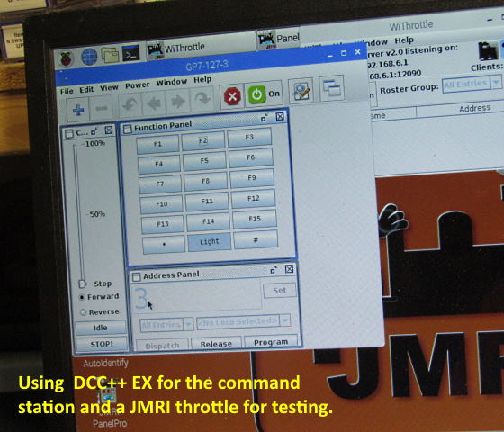
….. connected to the track which is connected to an Arduino DCC++ EX command station. The command station is connected to a Raspberry Pi running Steve Todd's free downloadable image card that boots up JMRI automatically as shown above. I'm connected to the decoder with one of JMRI's throttle on address 3. I'm able to test all the functions of the decoder with the function keys and could also connect using JMRI's Decoder Pro and reprogram the engine number and any of the functions on the computer.
You can setup a DCC++ EX command station with your computer or a dedicated train room Raspberry Pi computer for under $100 ( HERE ).
Above or ( HERE ) you can see the decoder tester in use.
The next page will continue with putting parts together and wiring.
These parts are up on my thingiverse.com account ( HERE ).
=========================================
...........................On..............e.........Next Page If There Is One