.................................. Return to Sumner's Home Page....
Return to N Scale RR Main Menu........ Return to Decoder Install Menu
=========================================
..............Previous Page..............................Next Page If There Is One
=========================================
...........................--- Decoder Tester Part 2 ---
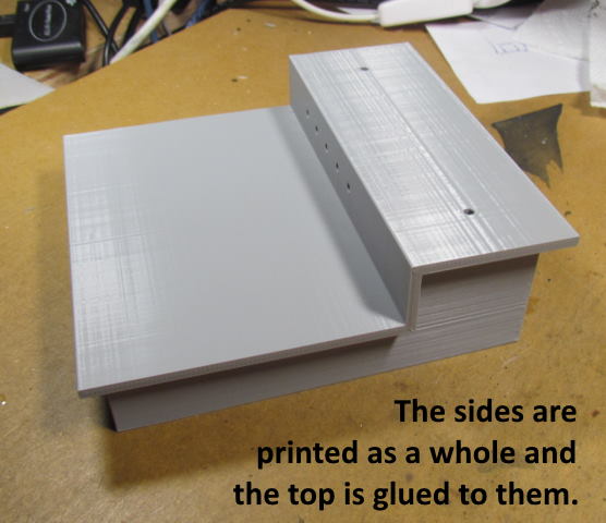
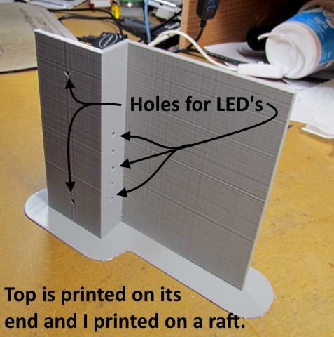
The first two pictures below show the top and the top glued to the base/sides.
.
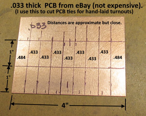
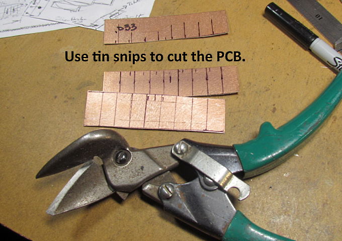
The following pictures will show cutting, drilling and preparing the solder pads for the wiring and the resistors.
.
.
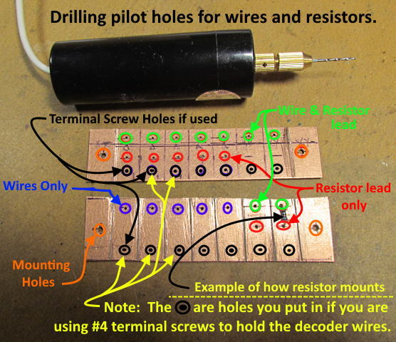
I labeled the holes above to show which are holes for the mounting screws, holes that a resistor lead along with a wire end will go in and holes that only get either a resistor lead or a wire end but not both. Also the black holes with black circles are holes you need to put in if you want to use #4 self-taping screws as terminal screws that you can put decoder leads under instead of soldering the leads on. Use the same bit as the pilot holes in the next sentence.
I drilled the pilot holes with a .037 bit but then ended up enlarging them to 1/16” (.0625”) with another drill and bit so you could just start with that size. I marked the holes where I wanted them along with where I wanted the isolation gaps in the PCB. I used a …
… center punch on the hole marks before drilling them.
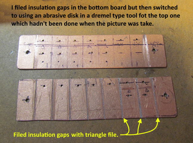
I filed the insulation gaps in the bottom board but thought I cold do it faster with an abrasive cutoff wheel in a Dremel type tool I have so switched to it. I wouldn't of been able to make the isolation cuts that go across the pads where the resistors mount with the file so the cutoff wheel worked quickly in all the rest of the cuts and would use it from the beginning if I was to do this again.
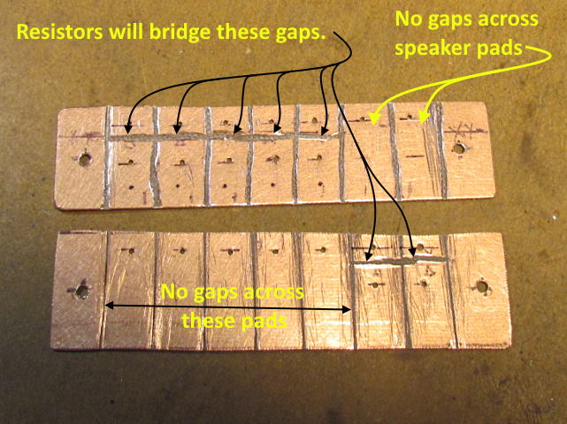
Above one can see all the final isolation cuts in both solder strips. The strip on the bottom above will end up behind the top one on the top of the tester when it is done.
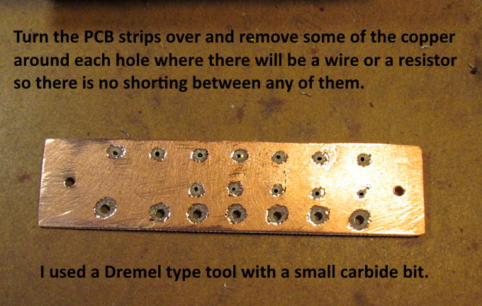
You need to also remove the copper on the other side of the board to avoid any shorting between any of the solder pads on the other side. There will be no soldering on this side but the resistor wires will protrude some along with possibly some of the wiring that is soldered to the opposite side.
The next page will go into putting parts together and wiring.
These parts are up on my thingiverse.com account ( HERE ).
=========================================
...........................On..............e.........Next Page If There Is One