.................................. Return to Sumner's Home Page....
Return to N Scale RR Main Menu........ Return to Decoder Install Menu
=========================================
..............Previous Page..............................Next Page If There Is One
=========================================
...........................--- Decoder Tester Part 1 ---
I had finished a number of decoder installs and hadn't had a bad decoder in any of them but decided to make a decoder tester so I could test or program a decoder before the install. That way I would know for sure it was working before going through the install. I'd seen some commercial decoder testers and some home brewed ones so decided at trying my hand at making one. While looking over what I've done keep in mind that you don't need a 3D printer to make one. The case could be made from other materials and you could decide on a different way to test the decoder. As an example look at what Brad did ( HERE ).
I wanted to be able to test up to 7 functions, depending on how many the decoder actually had. I also wanted a speaker so I could test a sound decoder and wanted a motor on the tester so I could make sure the motor controls were working. I came up with a design with two strips of solder pads that I could connect a decoder to in a few minutes. One strip had 7 pads on it for the basic decoder with the traditional 7 leads (red-right track power, black-left track power, orange-one motor lead, gray-second motor lead, blue-common positive power, white-forward light, yellow-rear light). The second strip also has 7 solder pads (5 pads for up to 5 additional decoder functions and 2 pads for the two speaker wires if it is a sound decoder.
The solder pads prove to be a quick way to connect the decoder to the tester and a quick way to disconnect it. I strip off about .1 of an inch from the end of each decoder wire. Tin them and then solder them to the appropriate pad on the tester. This only takes a couple minutes and un-soldering them takes even less time.
I designed the parts for the tester with Fusion 360 and printed them with my Ender 3 Pro printer. The parts were pretty basic and easy to design and print. Only the sides of the tester and the top were long prints. I printed the smaller parts using the highest quality and the two larger parts using standard quality. On the remainder of this page I'll show the parts as designed before going on to assembling and using the tester on following pages.
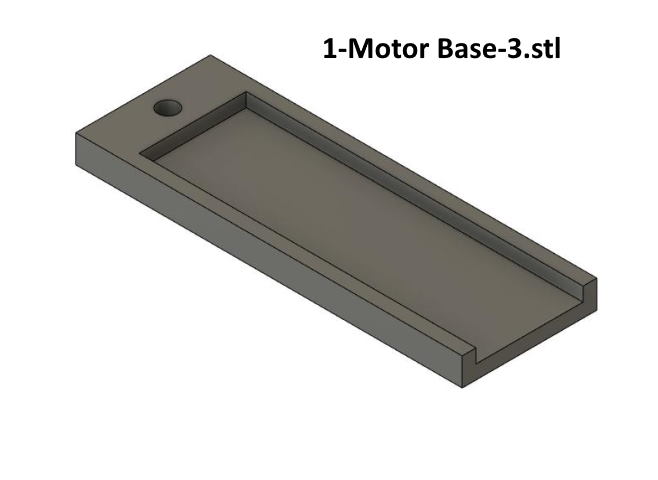
The part above along with the next three are used to mount a motor to the top of the tester. I had a motor that came from a N scale Intermountain SD45T-2 that had a broken frame. The mount was designed around that motor which appears to be the same basic motor as in some of the other loco's I have but I never measured them. If you use a motor that doesn't fit I'll leave it up to you on how to mount it to the decoder. The parts don't use much printer filament and are quick to print so I'd suggest printing them and seeing if they work for a motor you have. If they don't look at modifying them or coming up with something different.
The motor sits on the piece above.
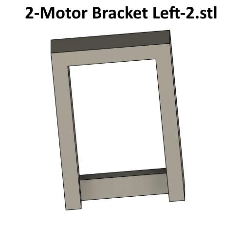
The motor slides into the piece above and up against the bottom stop.
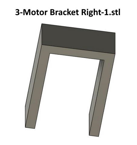
The motor slides past the piece above and into and against the previous bracket.
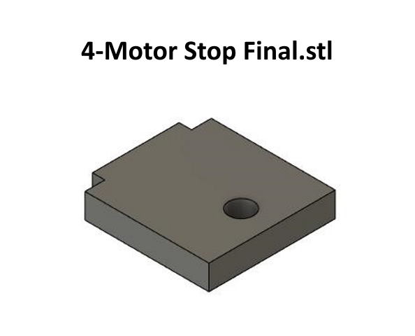
With the motor in the mount you slide this one against the bottom of the motor and it holds it in the mount using the screw hole.
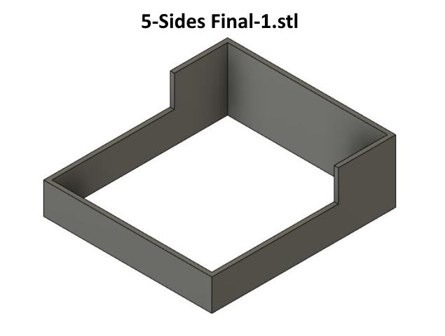
Above is the case sides.
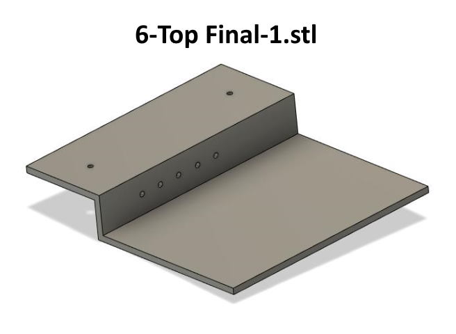
The top of the tester is shown above and is glued to the sides shown previously. The holes in the top are drilled out to accept two LED's. I put a while LED in the left one to represent the forward light on the loco and a yellow LED in the right one to represent the rear loco light if it has one. The motor mounts between the lights and will be show on a following page.
The five holes on the vertical part of the top are for 5 LED's to be used with any additional functions the decoder might have. If you toggle one of those functions on or off one of the LED's should light.
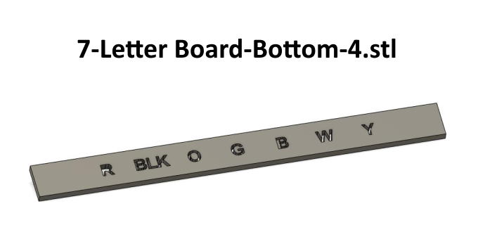
The next two prints, one shown above are glued to the top of the case and next to corresponding solder pads and are for reference as to which decoder wires should be soldered to each solder pad. The ones above are for the traditional 7 colored wires coming off of the decoder, left to right (Red, Black, Orange, Gray, Blue, White and Yellow).
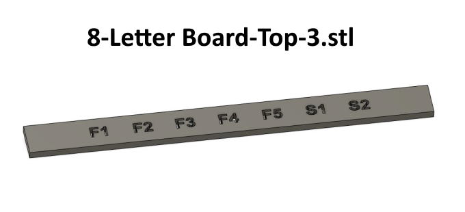
The letter board above is printed and glued next to the additional seven solder pads for the additional functions and the speaker wires if the decoder has them. From left to right ( F1, F2, F3, F4, F5 and speaker wires One and Two).
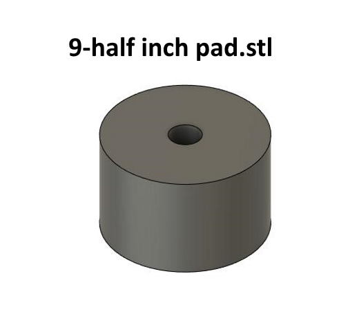
The print above is 1/2” in diameter and is glued to the inside of the tester case and you can screw another solder pad to it. You use that solder pad to solder all the common positive blue wires to. The blue wire from the blue solder pad which is the common positive from the decoder and then to the forward and rear LED's on their anode (+) side along with a blue wire to each of the five function LED's on their anode (+) side also. The rest of the wiring will be shown on a following page.
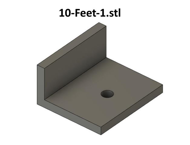
Last up are feet for the tester you can print if you so desire. I printed 4 of the ones shown above and will show how I used them on a following page also. You can glue them to the inside of the sides of the tester and use the screw holes if desired to mount the tester on a piece of lumber or whatever.
The next page will go into putting the parts together.
These parts are up on my thingiverse.com account ( HERE ).
=========================================
...........................On..............e.........Next Page If There Is One