.................................. Return to Sumner's Home Page....
Return to N Scale RR Main Menu........ Return to Decoder Install Menu
=========================================
..............Previous Page..............................Next Page If There Is One
=========================================
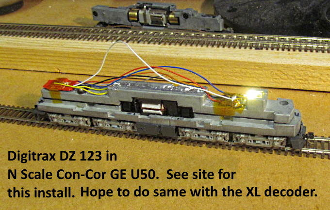
......--- XL Sound Decoder In Con-Cor GE U50 ---
UPDATE 06-09-21: After listening to the XL decoder I decided to get a better decoder for the U50. I ordered an ESU Loksound 5 micro decoder from Streamlined Backshop for the U50. It is a better decoder and I figured since I really like the U50's they deserved a better decoder. One big difference is that ESU has a sound file for the U50. The U50 had dual GE FDL-16 diesels and the sound file starts one and then the other. I decided to move the XL sound decoder to a GE U28C that I have and will document that on a separate page along with another separate page for the U50 install. I'll leave this page up for the other information it has about the XL sound decoder.
--------------------------------------------------------------------------------------------------------------------------------------------------------------------------------
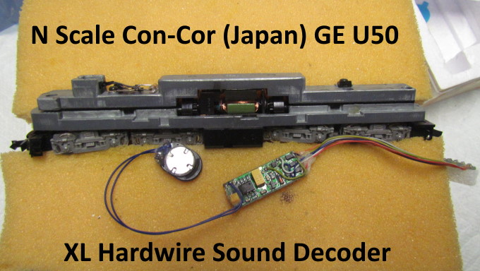
This was going to be a decoder install of a XL sound decoder in a Con-Cor GE U50 n scale loco. I've done three non-sound decoder installs in U50's and thought since there is a lot of open room in them I'd try a sound install in one of them first and had one I hadn't converted to DCC.
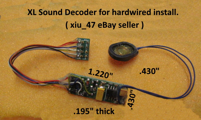
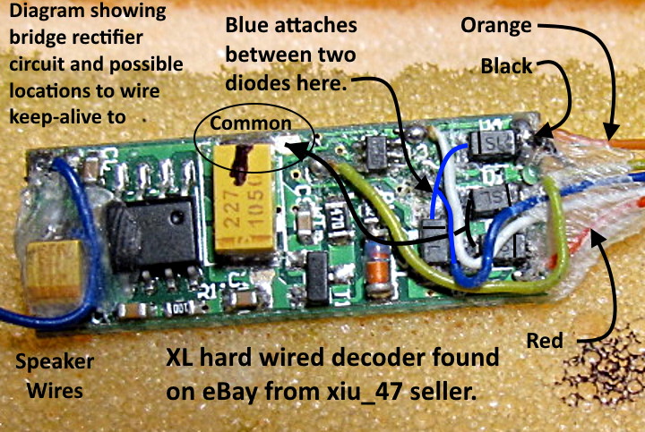
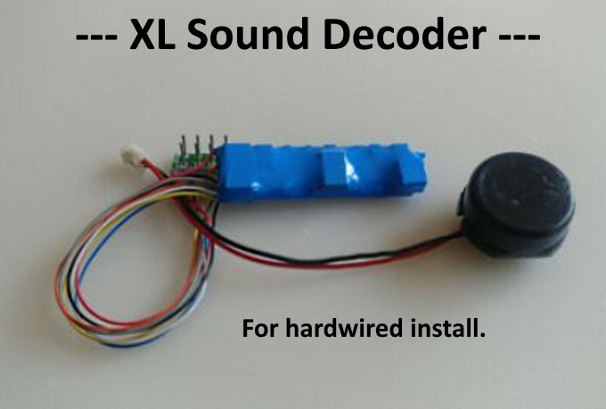
The sound decoder is on $40 on eBay from the seller shown in the next photo. I've seen/heard a couple videos of XL sound decoders in locos and thought I'd try one. I don't have high expectations for what I want out of a sound decoder at this point so I'll see how this goes before ordering more or trying a mores sophisticated sound decoder.
The seller shown above has a site for his XL decoders and has two eBay sites. I only found this decoder on the xiu_42 eBay site ( HERE ). The other two sites ( HERE and HERE ) show his kind-of drop-in decoders which seem to be the same as MRC decoders and he might be their supplier.
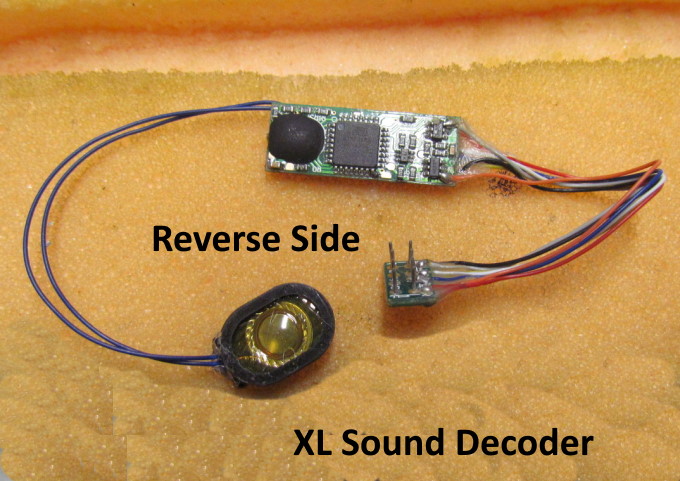
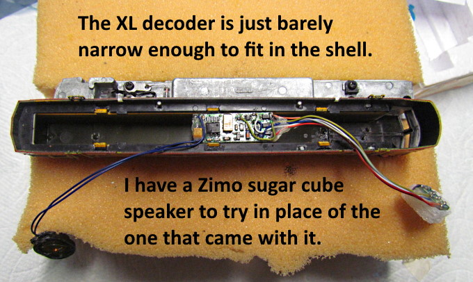
I'll be cutting the connector off and probably trying a different speaker from online advice from others that have used XL sound decoders.
.
.
Above is another decoder install I did on three U50's. You can find it ( HERE ). This should follow along similar lines.
I'm posting this as of 03-12-2021 and hope to do this install in the next week or so and will finish this up after doing that.
==== Possible use of a Keep-Alive ====
The next two pictures show how I plan on connecting a 'Keep-Alive'/'Stay-Alive' if I decide to use one with this decoder.
NOTE: At the time of writing this I have not done this so proceed on your own using the following only if you feel it is workable. I feel pretty confident that it is all correct but take no responsibility for what you might do. Also the soldering is not going to be easy on the decoder for the negative wire.
On the right end of the decoder above is the bridge rectifier circuit. It is comprised of the four square diodes with 'SL' on their tops. I also enhanced the lines you will find going across them that reference how they are oriented in the circuit. I found reference to how to attach a 'Keep-Alive' to a MRC decoder on the Steamlined Backshop site ( HERE ). Please read that info if you are going to do this and note 'the MRC Decoder Orientation For Keep Alive' diagram you will find there. That is what I used to figure this out. I've just recently bought some items off the shop and will plan on doing more shopping there in the future. Good info there and the pricing seems to be good.
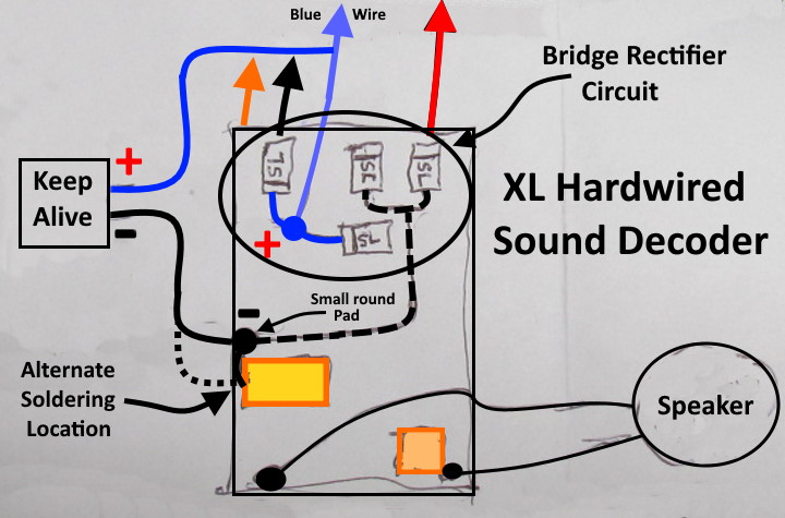
Above is a diagram of the decoder and the wiring as I found it. You might want to check it out and see if you agree. You might be able to solder a positive wire to the 'Keep-Alive' where the blue wire attaches between two of the diodes. Not much room to work there so the other option is connecting to the blue wire past the edge of the decoder at some point where it might go to your lighting. This is probably the route I'll take.
The attachment point for the negative 'Keep-Alive' wire is also problematic. You need to connect to a point on or between the two diodes in the upper right corner of the decoder shown above. Again I'm not going to try there as it is too crowded. I have traced that connection point to the left side of the decoder where there is a small unused solder pad or at least it looks like one. Not very large, but there, and the other option might be to the component right next to it.
Again only proceed with this if you feel good about what I have found at this point.
=========================================
...........................On..............e.........Next Page If There Is One