.................................. Return to Sumner's Home Page....
Return to N Scale RR Main Menu........ Return to DCC++ Menu
=========================================
..............Previous Page..............................Next Page If There Is One
=========================================
….......................................................--- WiTcontroller Throttle ---
.............................. --- GPIO Inputs Part 2 ---
============================================
.
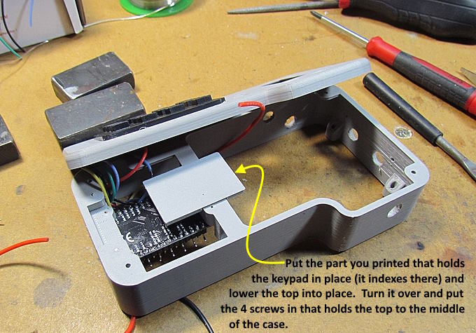
The bracket that pushes against the keypad lays on and is indexed by the cross-member. Set it on the cross-member and lay the case top down. Hold it there and turn it over and put the 4 screws in that hold the two pieces together.
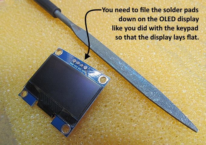
You also need to file the 4 solder pads on the OLED. That helps the display to lay flat in the case top.
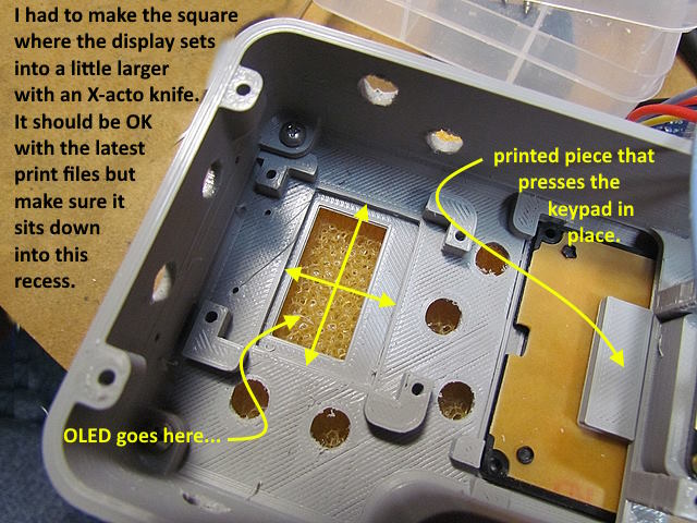
I had to enlarge the rectangular shaped area shown by the arrows above a little for the OLED to lay in there. I enlarged the area some on the current print files. Let me know if it isn't enough.
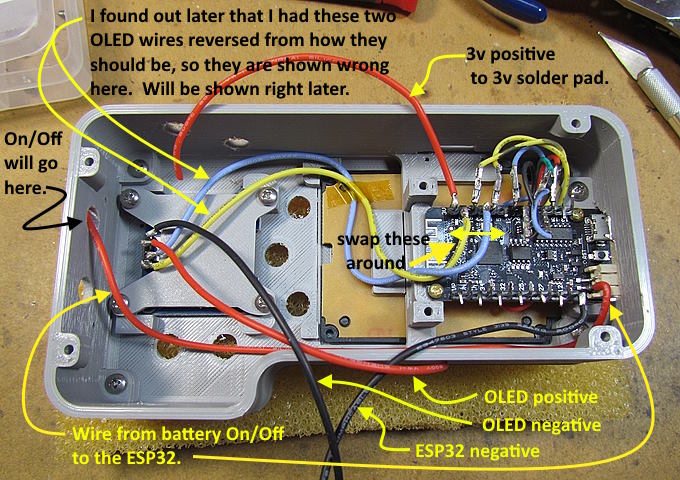
I screwed above with the two non-power wires that go to the OLED and got them on the wrong pins on the ESP32. This will show up for a few pictures going forward. The 'yellow' and 'blue' wires going to the ESP32 need to swap pins from what is shown above.
A charging port is optional as you can charge via the USB port on the ESP32. I added it as it was only a few dollars more and can now charge the battery without having the ESP32 on. Your choice but the following is what I'd recommend doing using the side port on the middle case.
NOTE: On the newest version of the throttle case I changed the middle section to have a 'true' 3 stage charging port vs. the USB port the original case had where you could charge using the protection circuit on the battery. After some research it looked like there were better ways to charge the battery so moved the port and recommend the following:
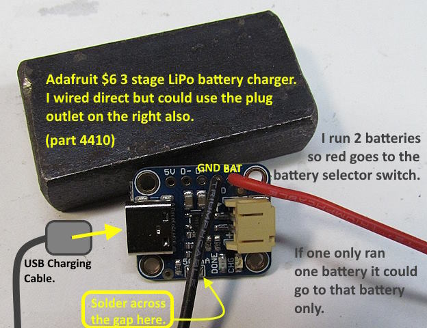
The WEMOS Lolin32 Lite ESP32 is capable of charging the battery/batteries but I like using the Adafruit 3 stage LiPo battery charger. It only cost $6 and is available from Adafruit or DigiKey. It comes setup as a 100mA charger but if your battery is over 500mAh you can solder across the 2 part pad at the bottom and it will charge at 500 mA per hour. Since both of the batteries I'll use are quite a bit over 500mAh I solder across the gap for the higher charging rate.
I can't find out much about the Lolin32 Lite's battery charging circuit but don't imagine it is as good at the Adafruit one. Also to use it the ESP32 has to be connected to a USB charging (5v) cord and the ESP32 itself is turned on while charging. I like the fact that for a few dollars more using the Adafruit charger the ESP32 can be off except when you are using the throttle.
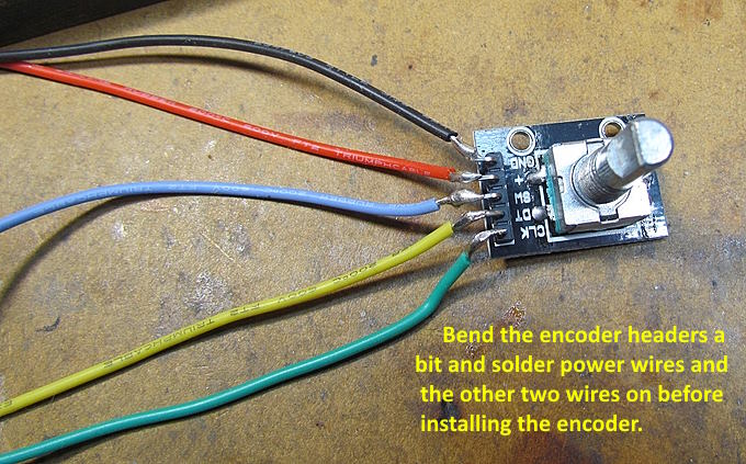
The encoder wiring is pretty straight forward. I put the wires on the OLED, encoder and all the switches this time before installing them. I measured with the wire itself from one place to the other in the case and cut it a little longer than that and soldered them to the components. This is easier and faste than doing it with the components in the case.
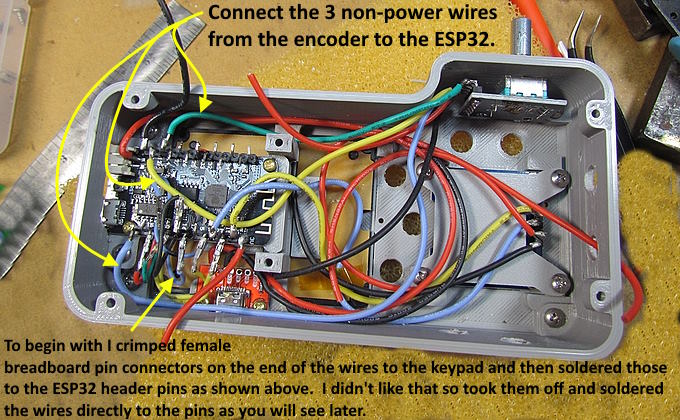
Soldered the 3 wires that go from the encoder to the ESP32. We will deal with the power wires for the OLED and encoder a little later. You will also note that I started with crimped on female breadboard pin connectors on the keypad wires to begin with. The wires were crimped and the connector soldered to the header pins. Didn't like it so you will see I changed that approach later.
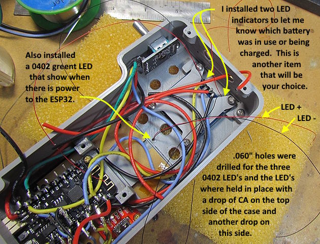
At this point I soldered the 0402 green LED's in. Would of been easier to do this before installing the OLED but it went fast.
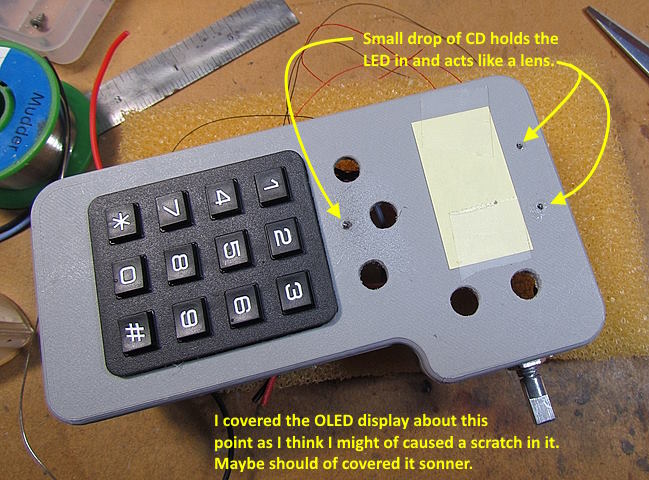
I think I got a very small drop of CA on the display so covered it for most of the rest of the build. I don't seen it now when using the throttle but sill a good idea to protect the display. It had a covering but took it off to put the display in the case and probably need to at that point.
…....... continued on the next page............
=========================================
...........................On..............e.........Next Page If There Is One