.................................. Return to Sumner's Home Page....
Return to N Scale RR Main Menu........ Return to HandCab Menu
=========================================
..............Previous Page..............................Next Page If There Is One
=========================================
….....................................--- HandCab WiFi Throttle – Part 3 ---
=========================================
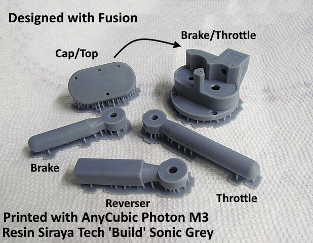
Assembly images......
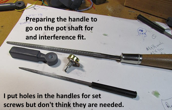
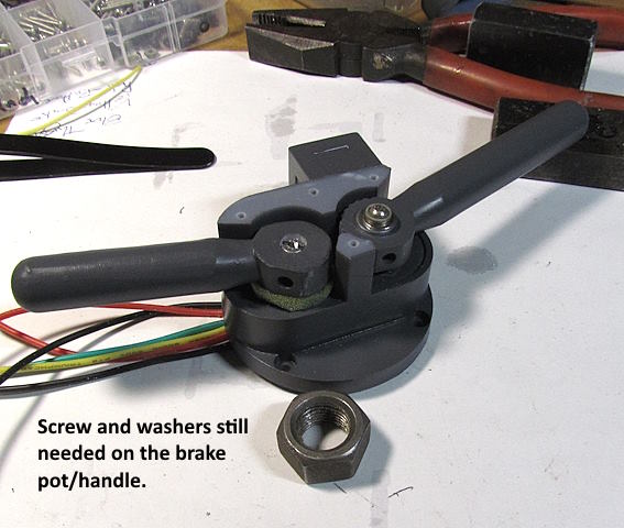
On this page we will mainly be working with the parts shown above.
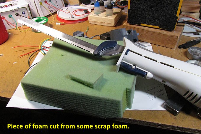
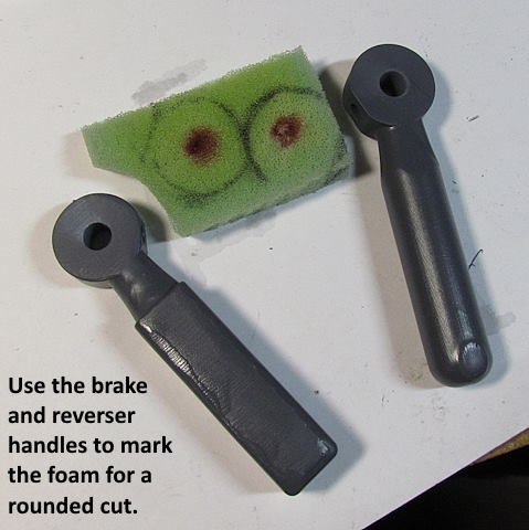
Lets start with preparing the throttle, brake and reverser handles to go on the pot shafts.
On the first throttle I build I used a file like above and also a small round file to take the holes out just a bit so that the handles would go onto the pot shafts. You don't want them loose. They should be fairly hard to push down the last bit onto the shaft. With the Siraya Tech 'Build' resin I'm using I haven't had a handle split pushing it down and I've pushed hard but could see where this could be a problem with some resins. If it is filament printed there is a lot more leeway on getting the hole the correct diameter. I've printed extra ones 'just in case' but haven't had to use them.
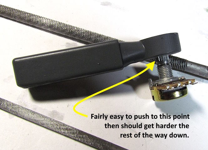
This needs to be an interference fit so that the handle always moves the shaft with it. The shaft moves easy so not hard to do this. I get the hole to where it is fairly easy to push down to the point in the image above but then takes some force to ….
… go the rest of the way down as shown above. Don't install the handle on a pot in the housing yet.
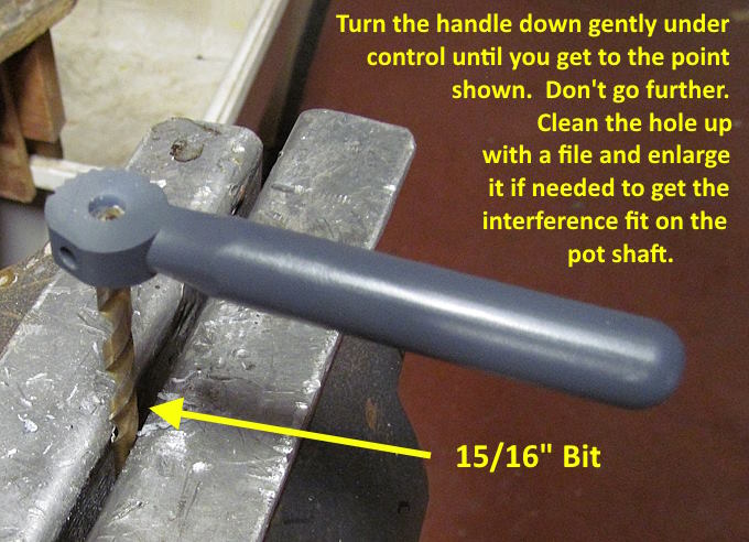
I've also done one set of handles as ….
….. shown above using a 15/16” bit. This is faster but use more caution in using it so as to not make the hole too large. Not a big deal if you print your own but if you ordered them from a printing service not so good. As I mentioned above if I was ordering the printing I'd get 2-3 of each as I doubt they would cost that much more.
Set the handles aside as it is time to install the pots...
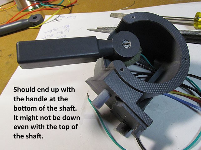
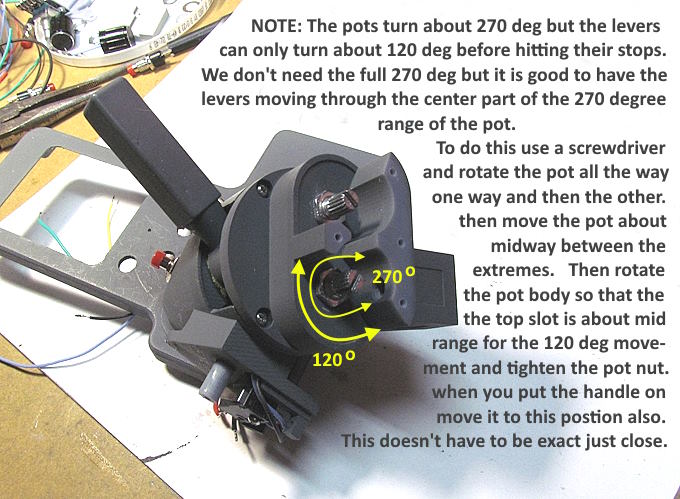
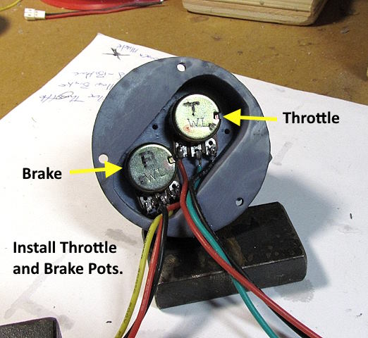
When you install the pots in the control stalk you want them positioned so that when the lever moves from one stop to the other stop it is operating roughly in the center of the pots range. The pot can rotate about 270 degrees but the throttle, brake and reverser levers only have about 120 degs of rotation before hitting the stops.
This is OK. Follow the instructions in the image above and remember it doesn't have to be exact where it is. You want to make sure that when a handle hits a stop that the pot isn't also at the end of its range in that direction. In other words make sure the pot itself isn't stopping the handle going in one direction or the other before it hits the case stop.
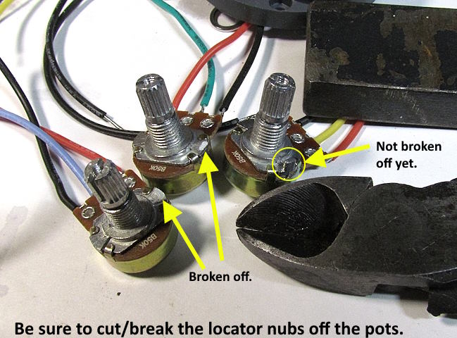
Make sure that the locator nubs/tabs that are on the pot body are broken off or the pot will be crooked or it might break the case when the nut is tightened.
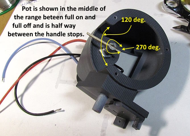
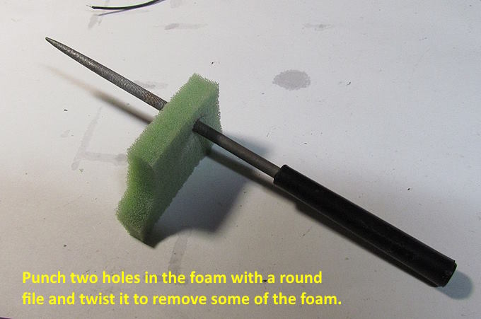
You can put the levers/handles on part way to test the range or use something else like above. Once satisfied tighten the nuts that hold the pots to secure them from movement.
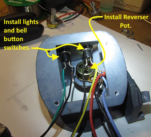
After the reverser pot is in install the 'light' and 'bell' button switches.
I clean the post for the lever up a little if needed but use a round file on the inside of the lever to enlarge it so that it swings freely on the post. Only takes a few minutes. You want it snug but free if that makes sense.
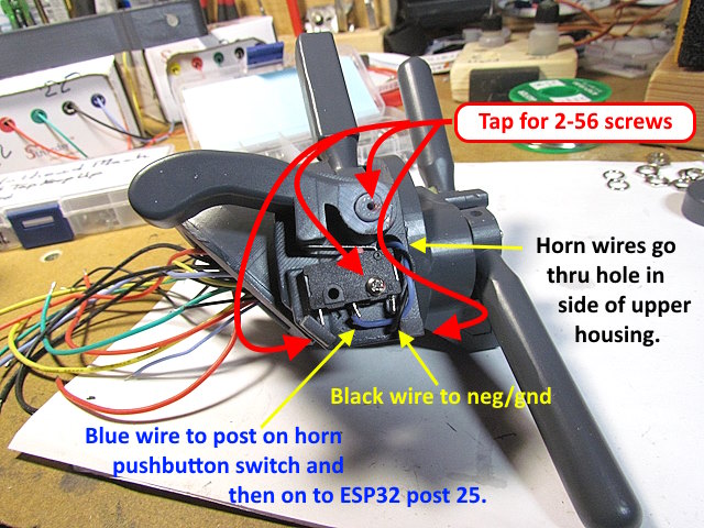
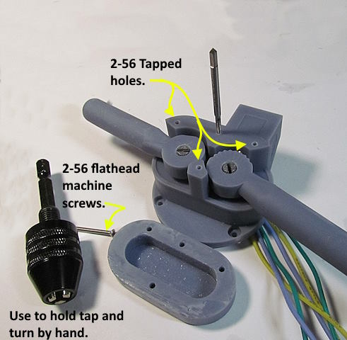
Install the limit switch for the horn on the side. Tap all the holes there for 2-56 screws. You don't need a screw in the left hole as the unused post on the switch can be bent (if necessary) to contact the screw tab there and that stops the limit switch from moving down along with the grip of the one screw that is used. I used #30 wires here to make it easier to thread them out of this area and down into the main case.
The blue wire goes down to the pushbutton switch for the horn and then on to ESP32 pin 25. The horn will operate from the control lever here or the pushbutton.
The 'brake' and 'throttle' pots can't swing 360 deg. in the upper housing but there is enough movement to position them so that the brake and throttle handles hit the case stops before going to the end of the pots rotation range. Don't worry that they aren't in the very middle of the pot's range. Just make sure they aren't at the end of the range.
.
.
.
.
.
.
.
.
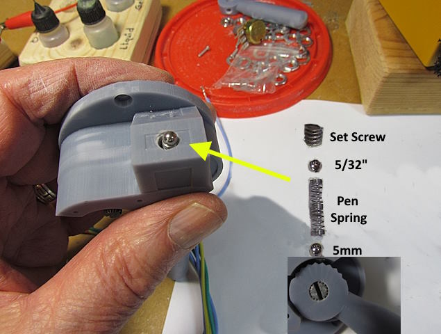
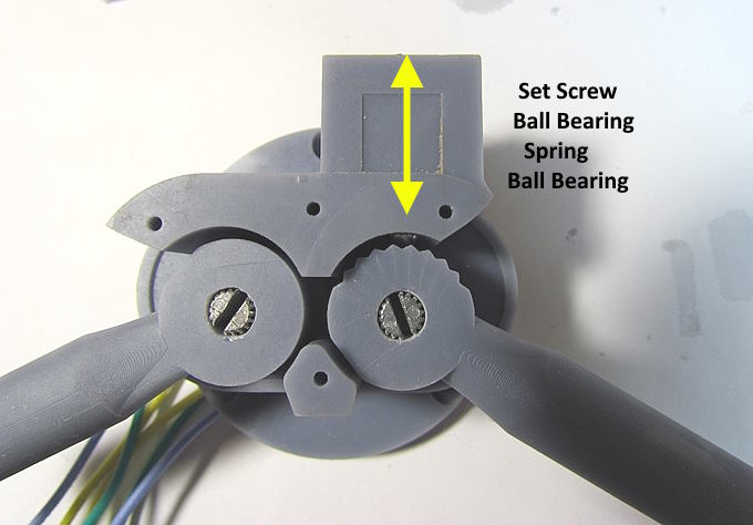
With the throttle handle installed you can move on to installing the following parts required for the detents to work.
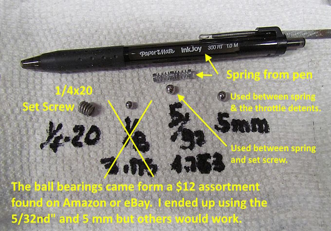
I started with a 5mm ball bearing (from an inexpensive assortment of bike bearings) on the throttle handle side and a 5/32nd on the other side of the spring (also from same assortment). On the second throttle I used a 5 mm on both sides. I'd try and go with the 5mm for sure on the throttle handle side.
.
.
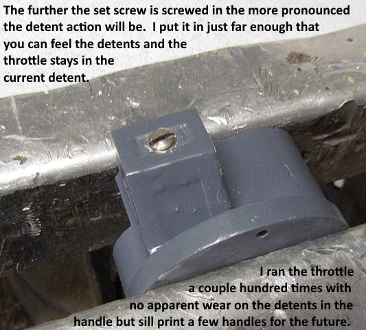
The set screw, shown above, sets the pressure of the ball bearing into the throttle handle's detents. You don't need to screw it way in. On mine just a bit more in than shown gives a good detent feel. Not much pressure to move the handle, you can feel the current detent and it stays in that detent. I ran the throttle through all 9 detents well over a hundred times and could see no wear on the detents. Still if you screw it in more than needed it might wear them out sooner. Print a couple extra throttle handles for the future so you have them if needed.
Also again this is using the Siraya Tech 'Build' resin so not sure about other resins. Filament prints should be similar to what I've seen here but not sure about the detent detail in the print with filament, I'd think it would be OK (I'll try and print a filament one).
You should of already tapped the holes for the top of the housing but if not do that now.
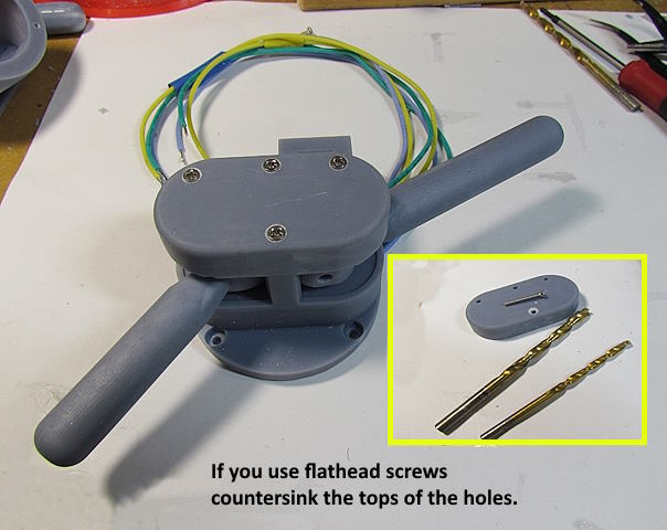
The top holes aren't recessed for flathead screws for those that want to use a different screw head. If you do use flathead screws use a countersink, what I use, or some drill bits to make a countersink for the screws heads as shown above.
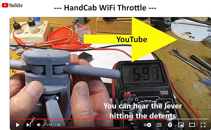
For a YouTube showing how repeatable the throttle is with the detents click on the image above or ( HERE ).
For the whole build of this throttle go ( HERE ).
=========================================
...........................On..............e.........Next Page If There Is One