.................................. Return to Sumner's Home Page....
Return to N Scale RR Main Menu........ Return to WiTcontroller Menu
=========================================
..............Previous Page..............................Next Page If There Is One
=========================================
….......--- Building Peter's WiTcontroller Throttle ---
.............................. --- Part 3 ---
=========================================
.
.
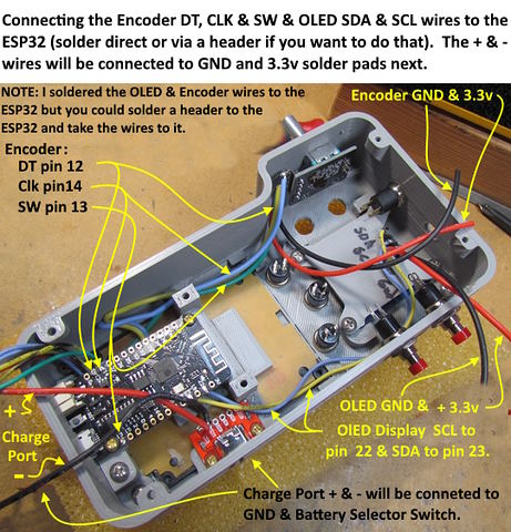
Above the DT, CLK and SW wires from the Encoder have been soldered to the ESP32 at pins 12, 14 and 13. I brought the wires up from the bottom with the board out of the case and soldered on the top side. I did the same for the OLED displays SCL and SDA wires to pins 22 and 23. At this point leave the positive and negative 3.3v wires for the encoder and display loose. They will be addressed with the next step.
An option is to solder a header to the ESP32 (you will see I did this later) and solder breadboard wires to the encoder and display terminals and put the female end of the breadboard wire onto the ESP32 header. In the long run soldering is probably more reliable.
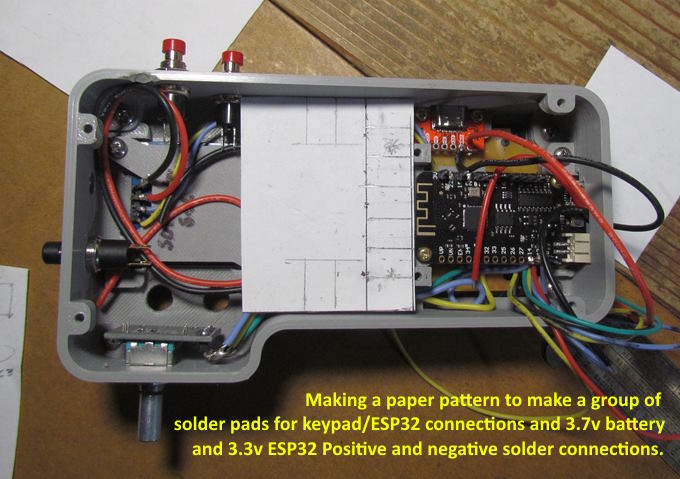
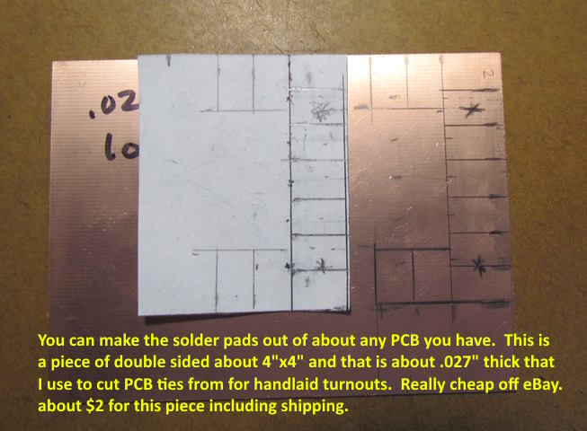
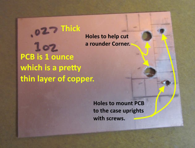
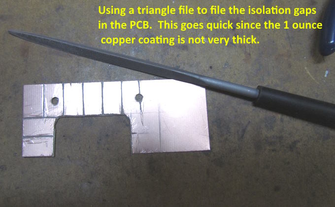
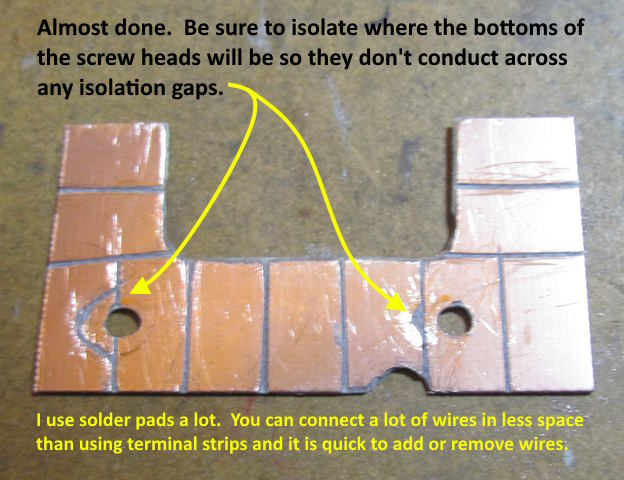
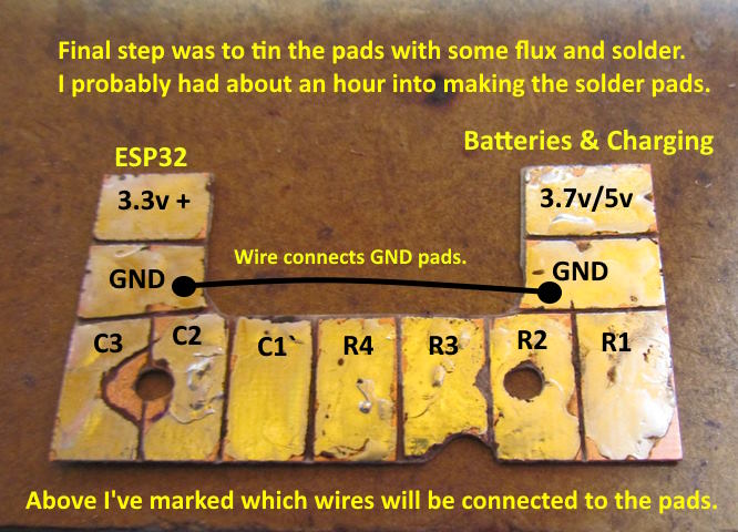
Next (above and following images) a number of solder pads will be made to solder keypad, ESP32, battery/charging and 3.3v positive/negative wires to.
.
.
.
.
.
.
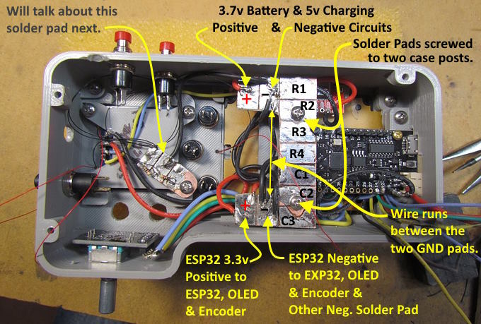
With the solder pads in place the encoder and display's 3.3v wires and battery/charging wires were soldered in place. Also the ESP32's 3.3v positive and GND outputs were connect to the solder pads at the bottom in the picture above. Also a GND wire was run between the GND (-) pads at the top and bottom of the solder pads to create a 'common ground'.
To be continued.........and if you came into this build here click ( HERE ) to go to the start of the build....Add
=========================================
...........................On..............e.........Next Page If There Is One