.................................. Return to Sumner's Home Page....
Return to N Scale RR Main Menu........... Return to Building UP's Canyon Division Menu
=========================================
...............Previous Page.............................Next Page If There Is One
=========================================
…............................................................. .--- This & That ---
============================================
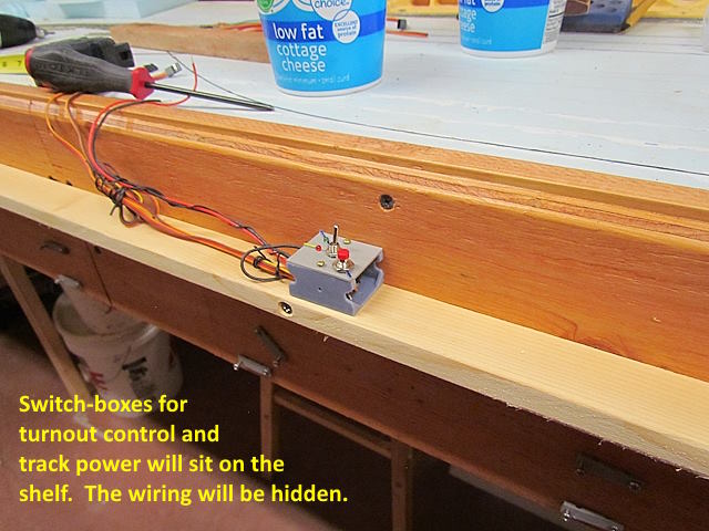
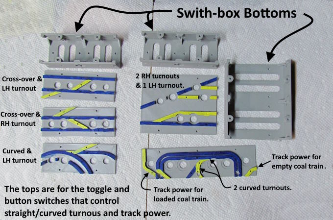
I finished the track wiring in the hidden staging but still need to connect the switch-boxes that control the servos. I have the switch box bottoms and some generic LH & RH tops up on my thingiverse.com account ( HERE ) that you can print out but not the ones shown in the next image. They are specific to turnout situations on my layout so unless there is a demand for them I won't be putting them up.
The boxes are about 1.5” long and 1.25” across and a little over 1” deep. As mentioned above I have some generic ones for LH & RH turnouts as I've made a ton of those in #6's. I usually add them together for cross-overs or use them tied to curved turnouts at times.
Above are some of the switch-box tops I've designed and printed for special circumstances. I only need one toggle and button switch to control the two servos that throw the two turnouts in a cross-over. In the tops at the left above there are holes for two toggle and two button switches for control of either two turnouts or three in the case of a cross-over and a turnout by it. The little larger box (top right) is for three turnouts in the hidden staging. The one below it controls two curved turnouts on one of the two coal mine tracks to the loading area. On the right there is a hole for a toggle switch that will turn the track power on/off for the track that holds the empty coal train and on the left will be a toggle switch for the track power for the loaded coal train.
It doesn't take too long (an hour or so) to design the tops for special situations and I enjoy doing it.
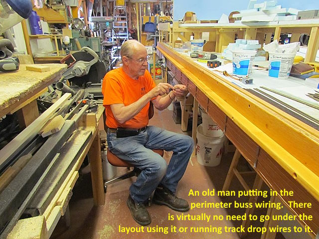
I thought I'd share a couple pictures of how I've been adding the drop wires for track power that go out to the DCC buss. I this is in the hidden staging so not much need to hide the wires but was practicing on the black wires. The red ones are running along the track here as they don't need to be hidden and go to switches that can turn the power on/off for the section of track they are next to.
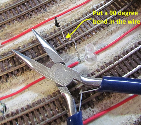
The black wires go to the buss on the layout's fascia. I drill a hole next to the track. The wire is 20 gauge solid. I push it down through the hole and reach under the layout from the side and pull it over to the fascia and put it through a 1/4” hole between the DCC buss wires there. I solder it to the buss wire (two images down). I then pull as much slack out of the wire as I want to back up at the track. Cut the wire from the spool and strip the end. Next I put a short 90 degree bend in the end of the stripped wire as shown above.
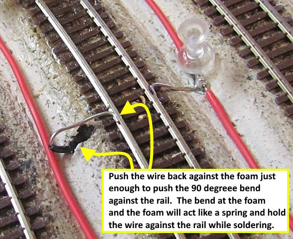
Next I push the wire back into the foam board just to the point I can bend the end down and lay the 90 degree bend up against the outside of the rail. I can let go and the wire stays there as the bend at the foam acts like a spring and holds the wire against the rail. I'll then put a drop of flux on the wire and rail and solder it. My go to solder now is Superior No. 30 Gel. I love it and highly recommend it. I wish I would of started using it much sooner. I use it for about everything including decoder installs. You can put it on a drop at a time and it works great. You can find more info on it and the link where to buy it ( HERE ), I'm just a very satisfied customer.
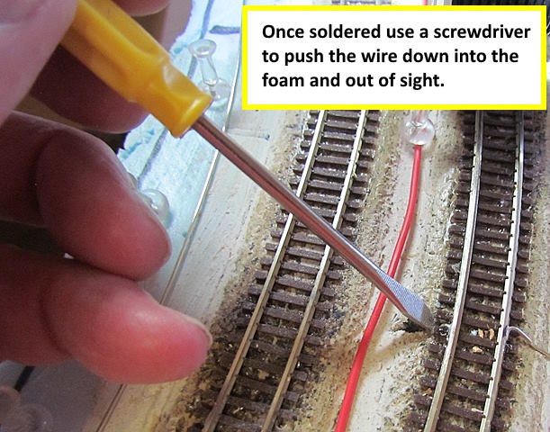
The last thing to do is to take a screwdriver and push the wire down into the foam next to the rail. I'm not adding ballast or ground cover here but if I would this would completely hide the wire except for the small solder joint on the rail side. I'm aware some will solder the wire to the bottom of the rail as an option. For my layout I doubt I'll take the time to do that as this basically makes the drop invisible. If I was doing a highly detailed scene I might consider soldering to the bottom but this is 'good enough' for me.
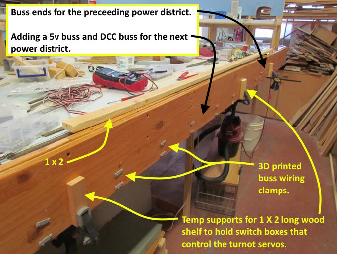
I can run 4-5 drop wires through a 1/4” hole and if I have more in the same area I just drill another hole. After having the DCC and 5v buss around the end of the layout now for some time I decided to go ahead and add it to the entire layout.
It has been working great and there is hardly any need to go under the layout using it for either the track wiring or the wiring for the turnout control that connects to the 5v buss above the DCC buss. If you dread having to go under the layout to do wiring you might consider it. At almost 80 it has been a lifesaver for me and I'm still able to get under there but don't like to.
In the staging I put the switch-boxes for the turnout and track power control up on the top of the fascia. For the rest of the layout I wanted something that would look better In the staging it hasn't been a problem on the top of the fascia but hasn't looked great. I did it there as there is the least amount of walking room next to the layout.
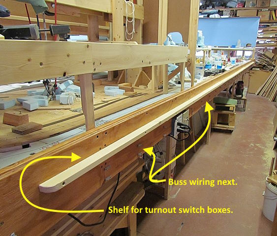
I considered different options for the boxes but finally settled on putting a narrow shelf on the side of the fascia above the buss wiring as shown above.
The switch-boxes will be screwed to the shelf and the wiring will go out the bottom of them to the buss and also through holes in the fascia to the servo controllers and on to the servos or to track sections if they are controlling track power.
There will be a shelf similar to this on the other side of the layout also.
Above I'm installing the two busses going down this side of the layout. Next I'll install it on the far end and down the other side also. It goes pretty quick (a couple hours for this side) and I can do a lot of it from the chair with rollers and none of it under the layout. The layout is 6 feet wide with a divider down the middle. So the maximum reach to grab a track drop from the side is about j30 inches.
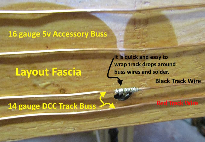
I pull the drop over to the side and run it through a hole between the DCC buss wires. Strip and wrap it around the buss wire and solder it. Quick, easy and a good solid electrical connection to the buss. At the track rail pull as much slack as you want out of the wire, cut, strip and solder the wire to the rail and the drop is done. No going under the layout and having to solder overhead or make connections in awkward positions under there.
A link to this whole build ( HERE ).
=========================================
...........................On..............e.........Next Page If There Is One