.................................. Return to Sumner's Home Page....
Return to N Scale RR Main Menu... Return to Test Track Menu
=========================================
..............Previous Page..............................Next Page If There Is One
=========================================
….......--- Wiring with a Perimeter Main Buss ---
=========================================
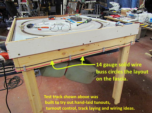
Before taking on my main layout I decided to first build a test track. Where I tested laying track, my hand-laid turnouts, various turnout switch machines, various switch machine controllers and wiring. When finished the test track will also be used for testing engines I buy, both DC and DCC. I can also use one siding on it to program DCC decoders that I've installed.
I covered most of the items I wanted to test on previous pages. On this page I'll cover wiring. I'm 77 (at the time of writing this) and getting older every day. I'm still fairly limber but don't like working under the layout and I'm sure that will only become more of an issue. I had to get under this test layout for a few minutes to install some of the switch machines but have also cut that time down by using some 3D printed fixtures I designed and printed that make installing the switch machines under the layout quick and easy. You might also notice that the test track is sitting on one side of my car lift so I could 'cheat' if I wanted and raise it at any time. I won't be so fortunate with the main layout so wanted to try something a little different in how I ran the main buss and other wiring.
I decided to try running the main buss around the perimeter of the layout vs. under it which is normally the case. Is it as attractive as a buss running under the layout. Of course it isn't but I don't care. If it extends the time I can enjoy the layout and make wiring it a lot easier than that is number one for me. As you move through the pictures below keep in mind I never had to once get under the layout for any wiring. Track and frog feeder wires were dropped through holes that were drilled from the top next to the track. They were soldered onto the track (each section) or the frog. I'd reach under the layout from the side and bring the drops to the side of the layout and run them through a hole in the fascia and solder them to the buss, a control panel or a limit switch for those controlling the frog polarity. Easy to do and almost all of the connections were made right at the side of the layout.
I'm so happy with this that I'll use the same procedure on the main layout with a perimeter buss for each power district.
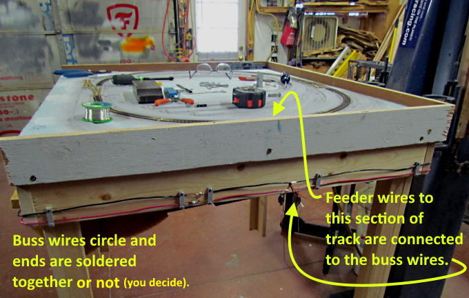
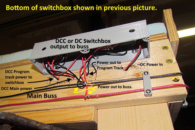
In my case the buss circles the whole layout and ….
…. each buss wire is soldered to itself at the completion of circling the layout. Above on the right you can also see a set of track feeder wires that have been brought out to the buss and will be wrapped around the buss wires and soldered.
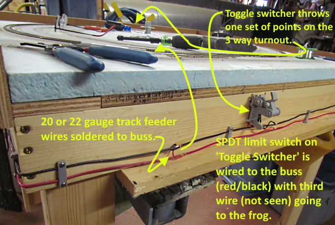
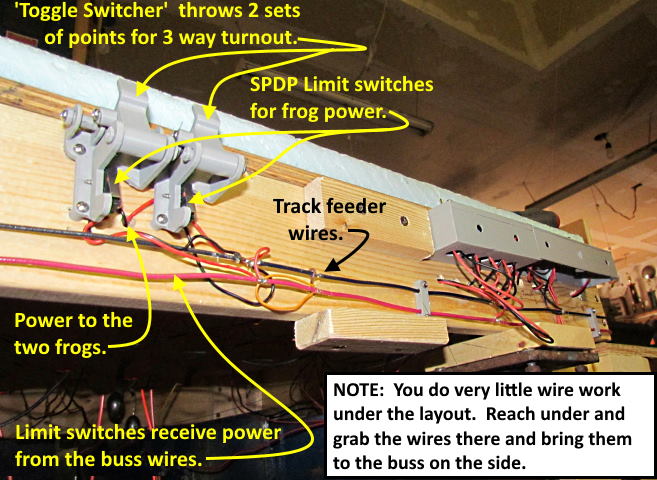
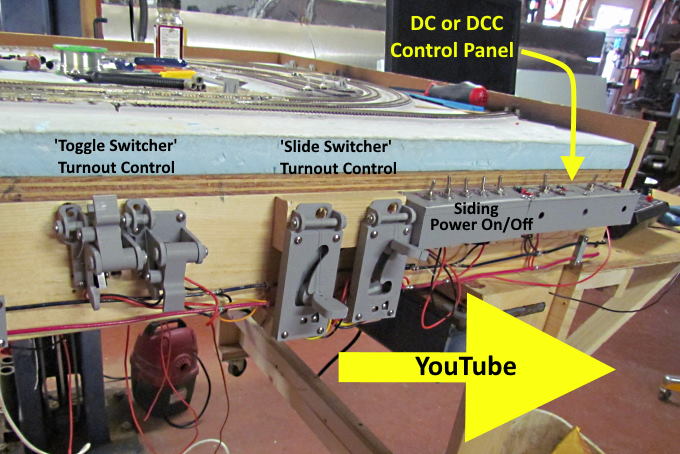
The 'Toggle Switcher' on the right controls one set of points for the 3-way turnout on the far side of the layout. More on how it works ( HERE ). Another one was installed to control the other set of points on the 3-way turnout later.
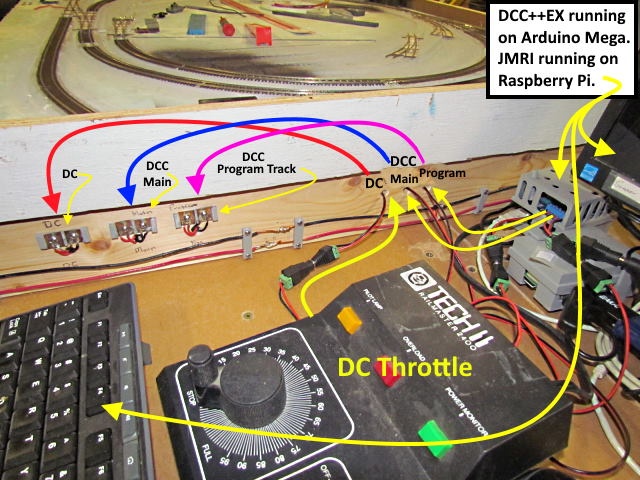
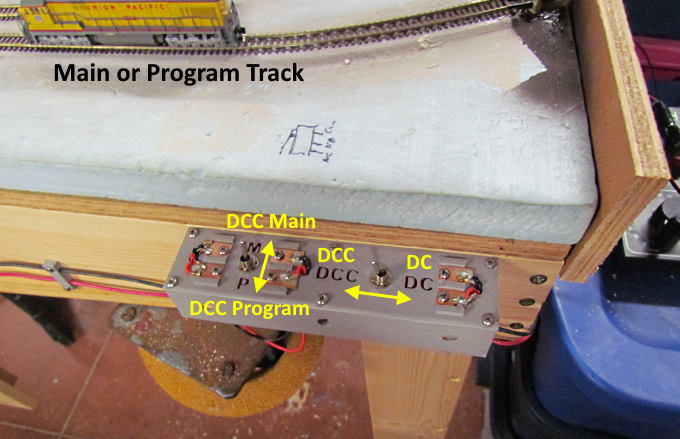
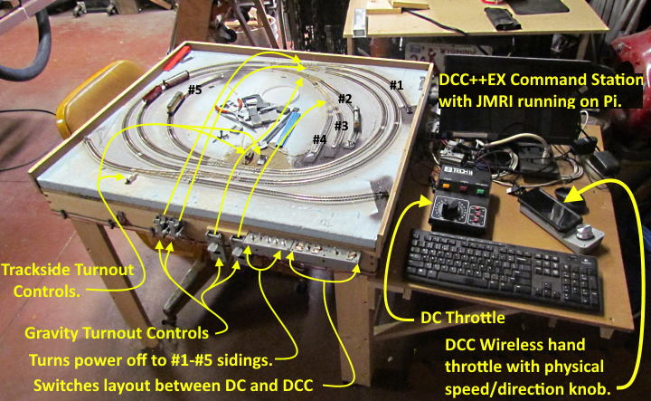
The layout can be switched with a toggle switch between DC or DCC. The DCC is the free DCC++EX running on an Arduino Mega that is connected to a Raspberry Pi running JMRI --- Command Station with computer. All of that for under $100.
The DC throttle, the DCC 'main track' power and the DCC 'program track' power all connect to the green/black quick connect plugs show above. Those wires then go into the fascia and run a few inches to the left and come back out and connect to 3D printed solder pads. The power then goes from the solder pads back behind the fascia to....
….. a main control panel on the side of the fascia shown above.
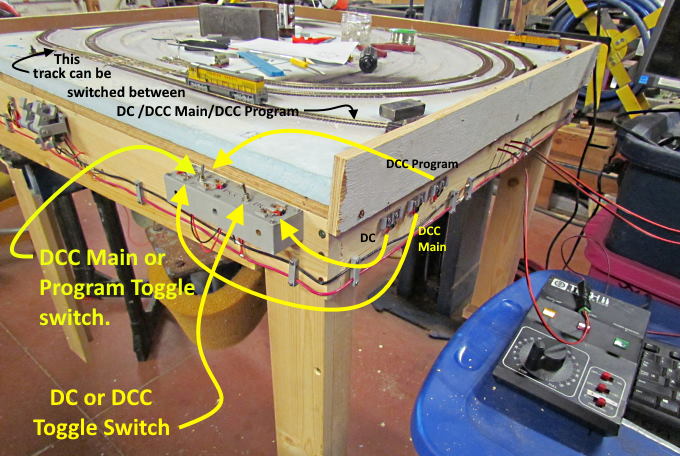
The control panel lets you change the main buss (track power) between DC or DCC. It also lets you change the section of track shown above it to either DC, DCC 'main track' or DCC 'program track'. That lets you program a decoder on that track with JMRI and DecoderPro and test it on the track or run it out onto the rest of the layout.
Power goes from the solder pads around the corner to the control panel and from it to either the main buss or to the program track.
The buss running on the fascia makes it easy to run track power to either sections of track or to something like the 'toggle switcher' (above left).
Wires from the frogs on 3-way turnout on the far side of the layout were soldered to the frogs and then dropped under the layout. I'd then grab them and pull them over and run them through holes next to the 'toggle switchers' and on to the SPDT limit switches that changed the frog polarity. The limit switches picked up track power from the nearby buss.
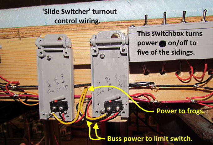
The 'slide switcher', ( HERE ) shown above, were also wired to the buss, limit switch and frogs.
Also the 'hidden switcher' ( HERE ) that uses a SPDT slide switch next to a turnout where also wired to the buss and the turnout's frog that they controlled. Again none of this required going under the layout.
For a YouTube of the 'Toggle Switcher' and the 'Slide Switcher' in use click ( HERE ) or on the image above.
I'm really happy with how the perimeter buss works for me and will be using it on my main layout. Might be an option for you if working under the layout is becoming hard for you.
=========================================
...........................On..............e.........Next Page If There Is One