.................................. Return to Sumner's Home Page....
Return to N Scale RR Main Menu........... Return to Building UP's Canyon Division Menu
=========================================
...............Previous Page.............................Next Page If There Is One
=========================================
… …-- Track Plan and Laying Out Track Centerlines ---
============================================
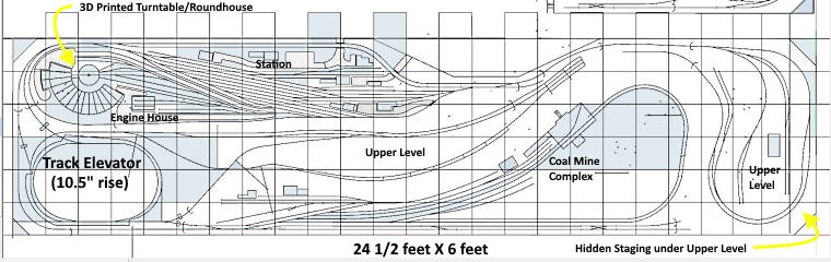
After getting all the 1” foam board laid down on the lower level I wanted to mark the track centerlines for most of the layout. First for the lower level and then once I knew where most of it was going to be I could move onto marking the upper level out so that I could cut it free and move it up 10 to 11 inches.
I've done all my track design using an older free version of SketchUp (CAD program that I think you can still download a free version of). I'm not using any sectional track (all ME flex track) or commercial turnouts at this point so I'm fairly free to design what I want and change things as I go. The drawing above is recent but only about 90% of it shows final track position. As I go from it to the layout I often see that I want something different and I'm free to change the plans.
Not shown but a nice feature of using the CAD program is that I can locate any place on the track plan with a horizontal and vertical distance off any corner. As I layout the centerlines I go into the house and use the program to tell me where the end of a track is in relation to one or two of the edges in just a minute and go back out and take that measurement to find the position on the actual layout and use it if I want to, very handy feature. If one is using sectional track and doesn't have quite that much freedom then one of the track planning programs that can use the track they are using is probably a better way to go but if you use flex track and build your own turnouts a CAD program can be much more flexible.
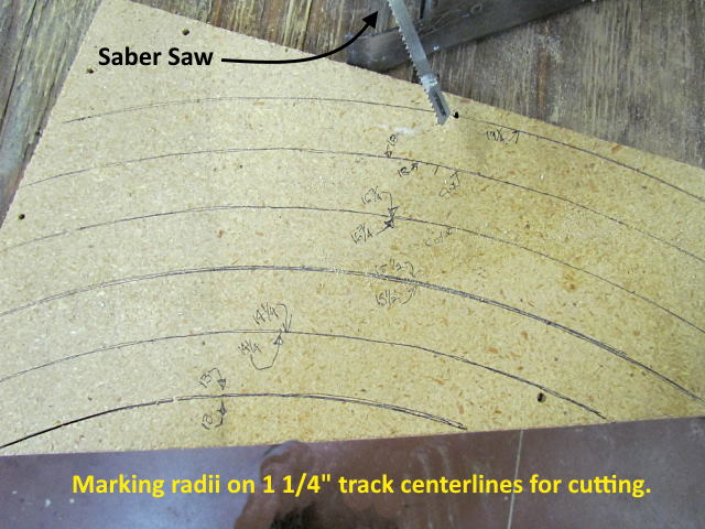
I use the 3D printed compass (next picture) to throw most of the track radius's as I laid out the track centerlines. At times though you need to swing an arc/radius from a point off the layout. To do so I've clamped a piece of wood to the side of the layout extending out far enough to use it for the compass pivot point. Still I realized that having some patterns of different radius would be handy so took a scrap piece of particle board I had and swung different radius's.
I'm using 18” and 16.75” radius for my main line whenever possible so started with those and then went up and down in 1.25” increments as that is the distance I'll use for track centerlines. I might of gone more if I was using newer equipment but my time frame is pre-1975. UP had some long locos in that time period but felt those radius numbers for the main line would be a good compromise between looks and functionality.
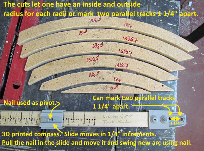
Above we see the new patterns and the 3D printed compass that is quick and easy to use in most situations. You can buy similar templates but these only took about 30 minutes to make and were basically free.
I ended up using these a lot while laying out the track centerlines.
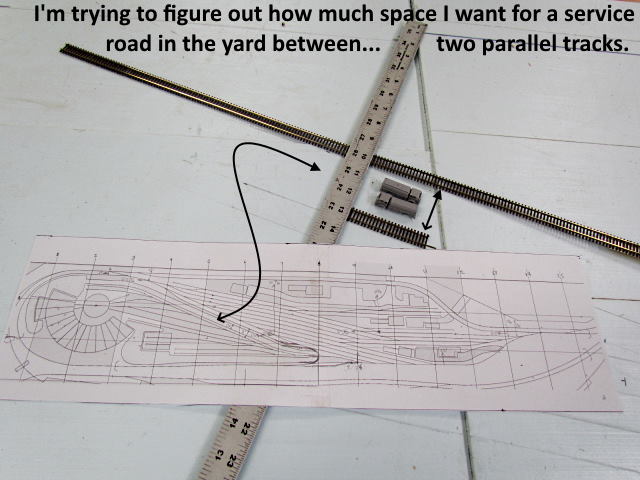
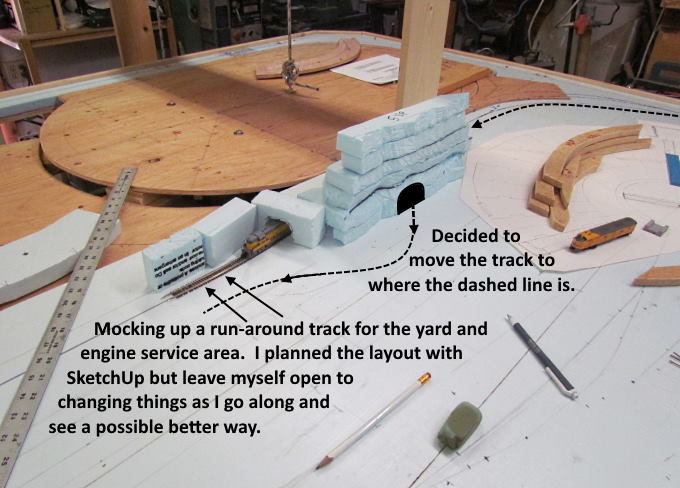
I had my plans but was easily open to making changes like above where I wanted to run a service road down between the main yard tracks and the area that has the turntable/roundhouse and other engine facilities. I used one distance designing with the computer and another in actuality. I made a number of other changes around the half dozen industries that will be next to the main yard and some other places like around the engine house.
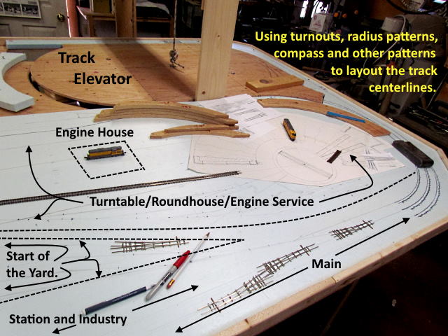
I use a couple 3 foot steel rulers, couple carpenter squares, angle finders, turnouts (mostly #6's) I've built, radius templates, compass, paper turnout templates and anything else that helps when laying out the track centerlines.
I also mocked up a section of a cliff face and a tunnel portal to get a feel for what my limits were on where my lower level track would be in relation to the upper level track is that will be about 10 ½ inches above it. When I laid out the track that runs around the back of the roundhouse (partially in a tunnel) I didn't like how it was coming out almost right under a turnout on the upper level. Laying it out with the CAD program I thought it would work. Once I had things in place I didn't like it so moved the track over to where the dashed line is relocating where it comes out of the hill side (further from the turnout above it). The dashed like is an approximation above and not exactly how it ended up.
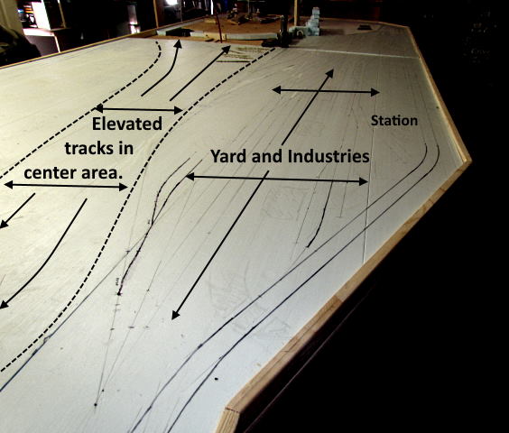
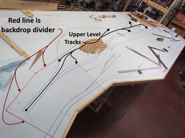
The elevated area in the center of the layout will have a backdrop/divider going down the center of it so that the yard scene on the right side above can have a different landscape (red-rock canyon country) vs. more high plains/mountains on the other side of the layout.
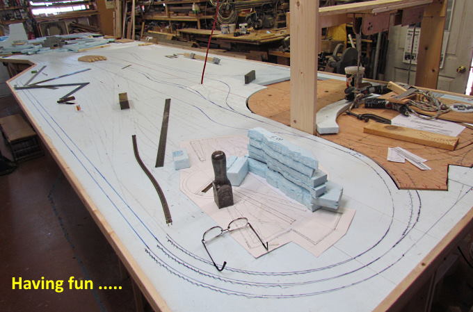
As the image say, I am enjoying doing this. Will it ever be done? No, but will be a good journey!
I still need to figure out exactly what I'd like to do on the left side of the lay in addition to the coal mine complex. I got far enough though to know where I wanted the upper level tracks on that side.
I still need to layout the upper level at the end of the layout above the hidden staging tracks. At this point it will be high country at the edge of the forest and I plan on having a saw mill there. Not one with a large log pond but more like what I've seen in dryer mountain states where the logs are trucked in.
To be continued …..........
=========================================
...........................On..............e.........Next Page If There Is One