.................................. Return to Sumner's Home Page....
Return to N Scale RR Main Menu.................. Return to Trackwork Menu
=========================================
...............Previous Page......................................Next Page If There Is One
=========================================
…......................…--- Track Laying Compass and ---
..... --- Tool to Shape N Scale Track to Curves ---
=========================================
You can find all the files to 3D print this object and others on my thingiverse.com account ( HERE ).
This is a tool that can help in a couple different ways in laying out your track plan on your layout's surface and helping to shape N Scale flex track to different radiuses. It is a compass that will make it easy to swing and mark curves of about any radius prior to laying roadbed and the track itself. Second it is also a tool that will help you shape your track to those radiuses.
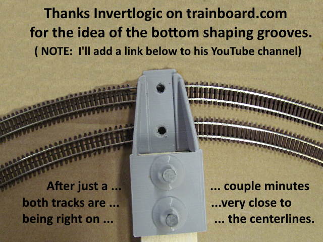
A big thank you to Invertlogic (sorry don't know your name) for the idea of grooves at the bottom of the compass to also shape a track to a desired radius. I have a tool that does the same ( HERE ) and ( HERE ) but it is doing the process freehand. After build the tool below I found I could shape a track to a desired radius in seconds and it would be almost exactly right on the desired radius.
Here is a link to Invertlogic's YouTube channel ( HERE ). Check it out as he has many great videos and has a wonderfully detailed 2' X 4' layout that is exceptional. You can also find the video that inspired making the tool below ( HERE ).
=========================================
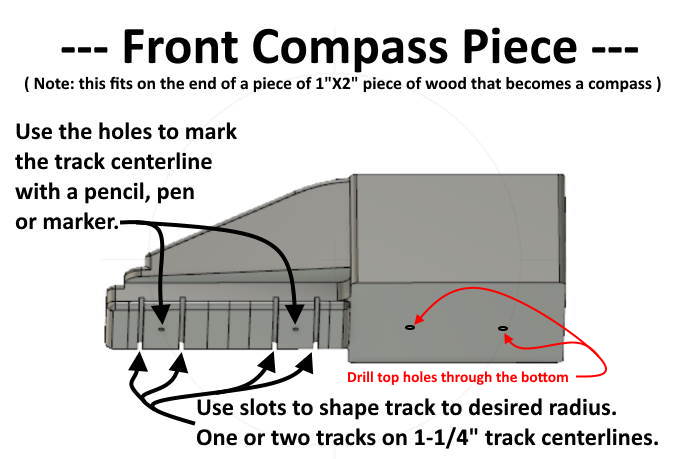
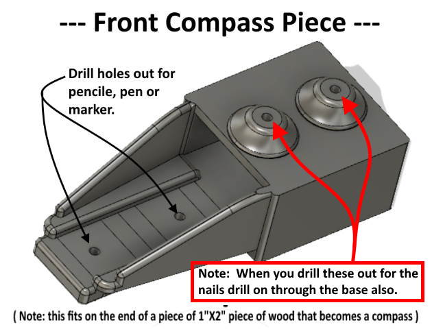
NOTE: The 3D printed pieces below will slide onto a 1 X 2 inch piece of lumber. Most places a 1 X 2 will actually measure out to be 3/4” (.75”) X 1-1/2” (1.50”). 1 X 2's are very common but if not you could always cut down a larger piece of lumber to the right size.
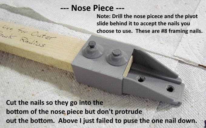
If the bottom doesn't have holes directly under the ones shown by the red arrows above drill them so that the nails that hold the nose piece above to the 1 X 2 go through the 1 X 2 and into the bottom of the nose piece. Cut the nail just short of protruding all the way through. Don't drill those holes out until you decide on the nail you will put through them so that you end up with a snug fit with the nail.
.
Drill the holes that go through the top and bottom to the diameter of the nail you will use for a good fit. You don't want the nail to be wobbly in the holes and 1 X 2.
.
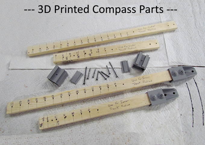
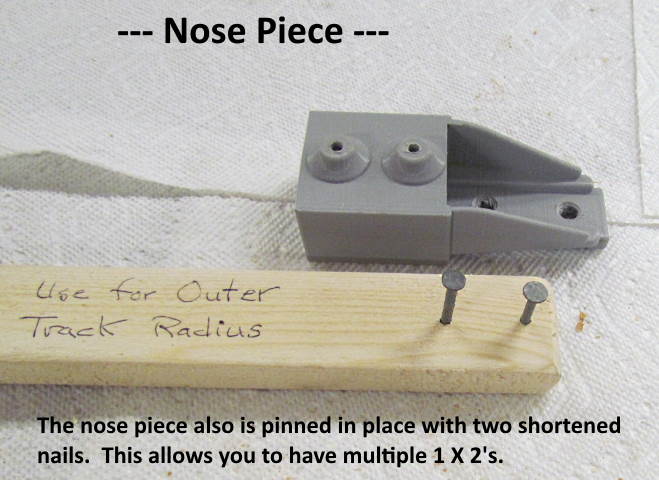
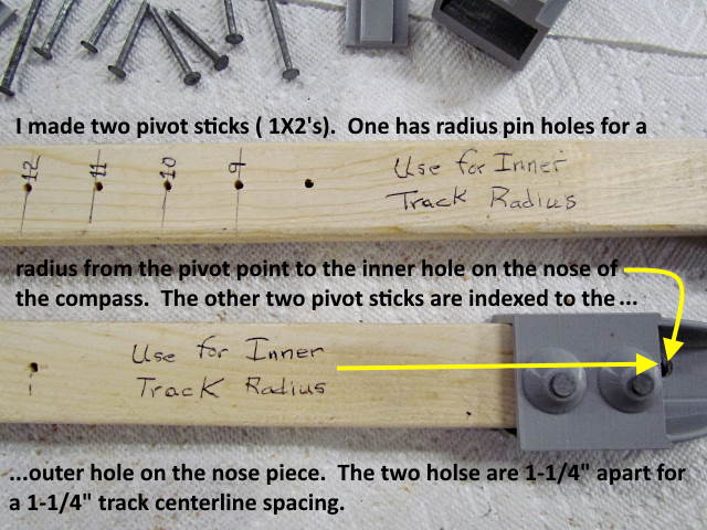
I printed up two nose pieces and two rear slides but if you pin them and don't screw the nose piece on you can have multiple 1 X 2's marked and drilled for different radiuses and just move the nose and slide to whichever one you are using at the time.
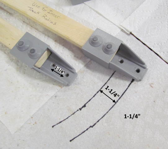
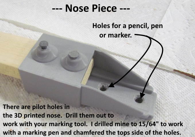
If you use the holes for two tracks they will be on 1-1/4” center-lines.
.
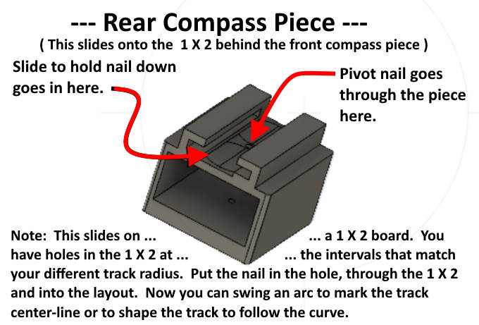
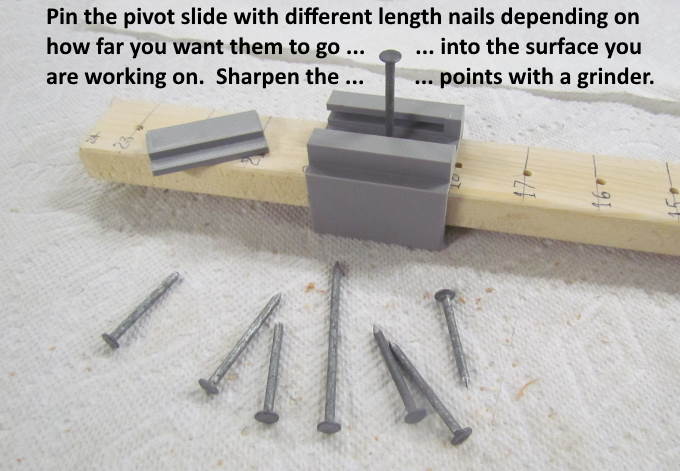
Cut nails to different lengths depending on the situation. I'd use long nails if you are sticking them into foam and short nails if you are pivoting the compass on a harder surface. I used #8 framing nails but you could use other nails. Just drill the holes in the printed pieces for a good fit.
.
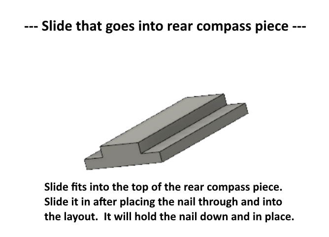
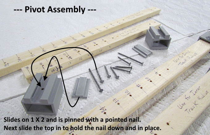
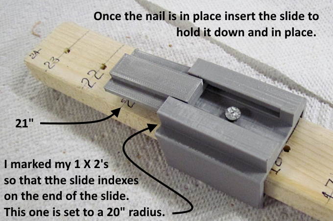
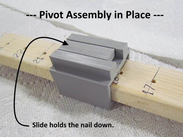
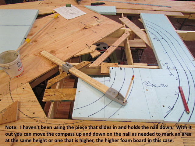
The slide in the top prevents the nail from sliding up if the surface is hard.
I started by screwing the nose piece to the 1 X 2 but switched to pinning it with the nails. That way it comes off easily and can be used on a different 1 X 2 that is a different length or has radius holes in different positions. It works as well as when I put wood screws in to hold it and is a lot faster to remove and put into place.
.
.
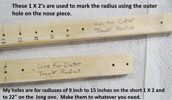
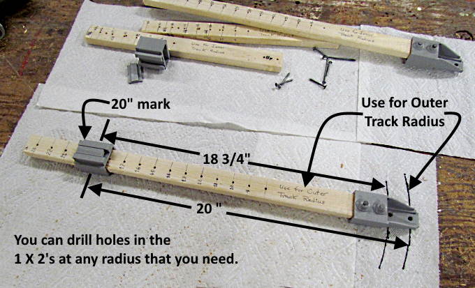
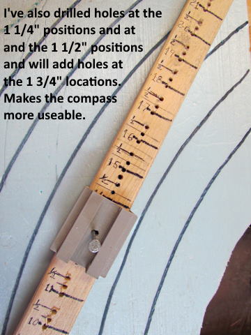
There are lots of options for the 1 X 2's that are used. The ones I have now are set up on 1 inch radius intervals except for a couple other spacings on the shorter 1 X 2 of 11-1/4” and 12-7/8” and 14-1/2” for a couple unique situations I have going on. I made the 1 x 2's in two different lengths so that I wouldn't be swinging the longer one for shorter distances and will still probably make one that is longer yet that won't be used in many situations.
I also have one set of 1 X 2's that has the radius marks/holes indexed to the outer hole on the nose and another set that is indexed to the inner hole on the nose. Depending on which is used the other track center-line if used will be 1-1/4” less than or more than the other track center-line.
.
.
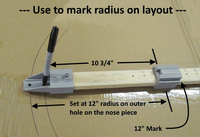
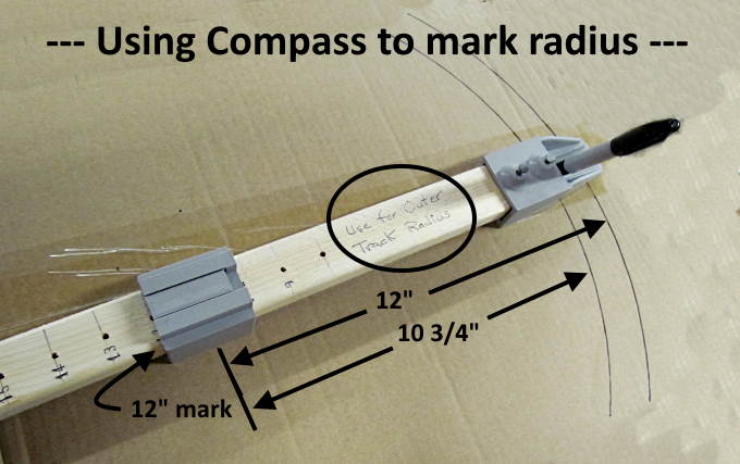
Above I'm using the surface of a cardboard box to illustrate the use of the compass. In practice this would be the top of the layout. If the 1 X 2 past the end of the slide gets in the way make one that goes only to the end of the slide. 1 X 2's are very cheap.
Be aware of which hole you are marking with as one will be off by 1-1/4” from your mark for the slide on the 1 X 2.
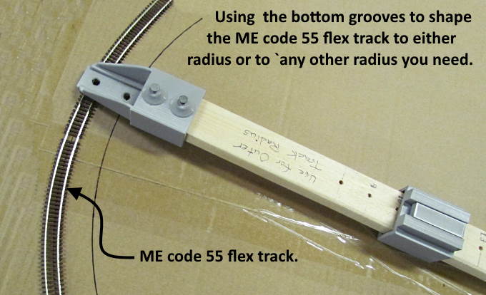
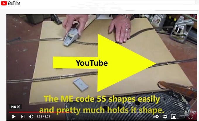
Using the rail grooves in the bottom of the compass it only took seconds to shape this piece of ME flex track to the desired radius. Depending on working conditions this could be done on or off the layout's surface.
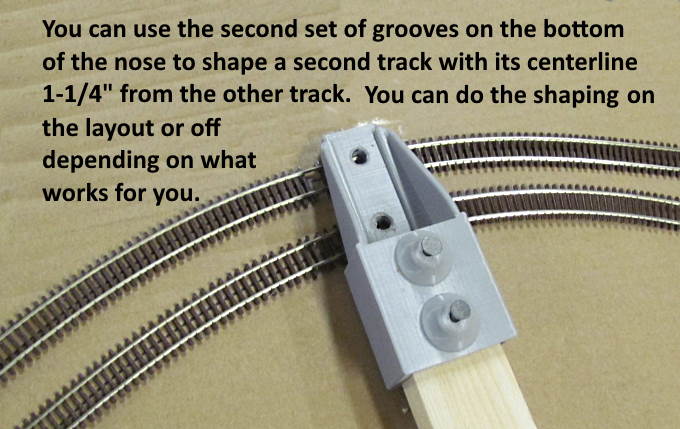
Above a second piece of track is shaped to lie inside of the first piece. You of course don't have to do these at the same time or with one in place to do the second one. If you are trying to shape a second track to an existing track and the first track isn't on a fixed radius as shown above you could use just the nose off the 1 X 2 or I've got another tool you can print and use ( HERE for 1-1/4' center-line ) and ( HERE for 1-1/8” center-line ).
.
.
.
To see how easy it is to use the compass go ( HERE ) or click on the image above.
Thanks again for Invertlogic for posting this idea on trainboard.com and on his YouTube channel.
You can find the files to print this on my thingiverse.com account ( HERE ).
You can find all the files to 3D print this object and others on my thingiverse.com account ( HERE ).
=========================================
...........................On..............e.........Next Page If There Is One