.................................. Return to Sumner's Home Page....
Return to N Scale RR Main Menu.............. Return to Trackwork Menu
=========================================
..............Previous Page..............................Next Page If There Is One
=========================================
a --- Using a Servo and Servo Tester for Turnout Control --- Servo for Turnout Control ---
=========================================
UPDATE: What follows on this page is my entry into servo control. Continue on if that interests you but you can find the final working servo tester ( HERE ).
=========================================
In my search for inexpensive and hopefully reliable turnout control I came up with the following solution. At this point I have only tried it on some test N Scale code 55 turnouts that I've made using a FastTrack's fixture and also from paper templates explained elsewhere on this site.
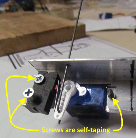
After seeing that others were using them I decided on servos for the mechanical part of the solution. I came up with a little different mounting solution than I'd seen but I'm almost sure that someone else has made a very similar mount for the servo and a limit switch. The limit switch will power the frog.
I'll need to make a lot of these so wanted to keep them as simple as possible. Instead of screws with nuts I found that sheet metal screws made a secure attachment for the servo and the limit switch. The top screw on the limit switch screws into the angle and the bottom screw bottoms on the angle and holds the limit switch in place after it has been rotated on the top screw to the proper position.
You can set the tension on the bottom screw where you can rotate the limit switch into the best location by hand and it will stay there when the servo arm activates it.
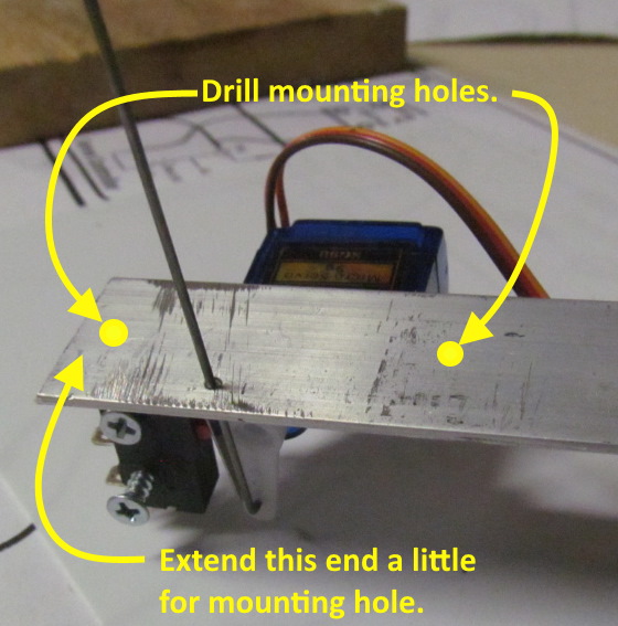
I mounted the servo on a long piece of 3/4” X 3/4” X 1/16” aluminum angle for testing purposes. I would mount a switch above it on a piece of plywood with a 1/4” hole in it, clamping the plywood to the angle. In order for the mount to be secured under the trackwork the angle needs to be a little longer on the left side for a mounting hole to be drilled along with another on the right side.
I'll make a jig to cut a number of these to length and then drill them in the mill/drill press all the same along with cutting a slot in one side for the servo.
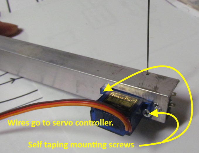
One nice feature of these servos is that they have the control wires attached. You can get extension cable cheap that will then run from the end of the wires shown to a servo controller.
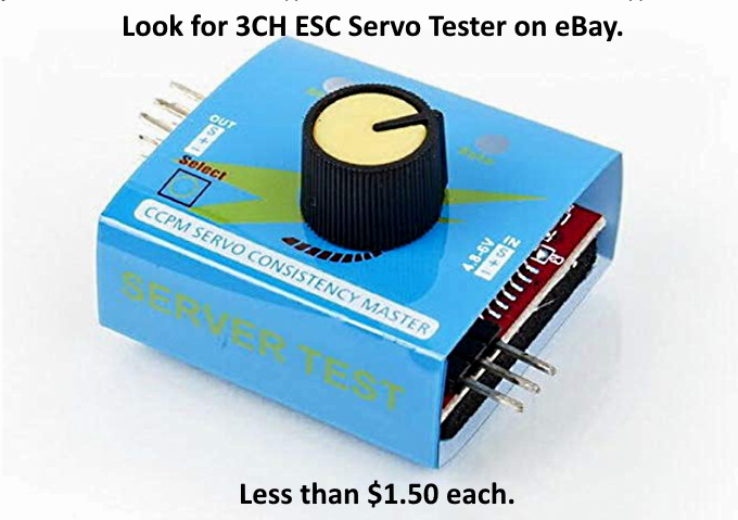
There are a number of servo controllers on the market to be used in applications where servos are used to power turnouts. They aren't real expensive but not real inexpensive either. If you aren't into making things yourself they are the way to go.
If you like to spend some time doing some electrical work then check out what Dave Bodnar came up with ( HERE ). Dave has done some great things in respect to model railroading and this is one of them in my opinion. He came up with an inexpensive solution to controlling a servo.
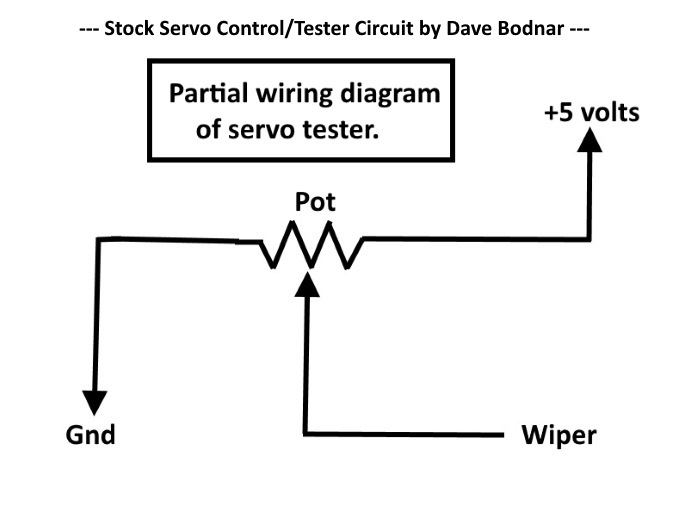
Above is the schematic of part of the circuit for the servo tester that he uses.
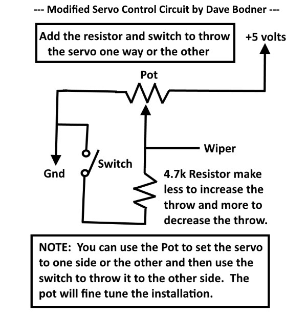
He modified it like above so that with the flip of a switch you can throw the turnout one way or another.
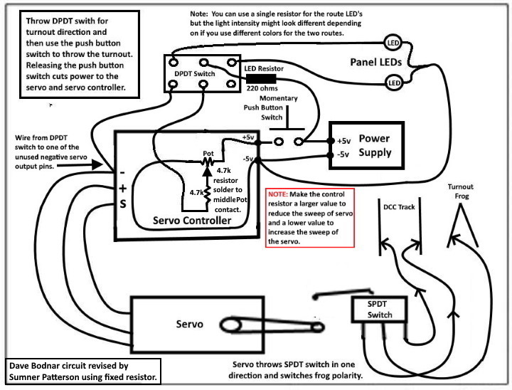
I took his circuit and modified it some more so that you have LED's showing the route the turnout is set for and so that the servo is only powered during the few seconds that the servo tester/controller is actuating the servo to throw the turnout.
Using the circuit above you have to determine the value for the added control resistor so that the turnout is thrown the correct distance depending on the track gauge you are using. As long as all your turnouts are the same and require the same force on the piano wire and the servo is mounted the same distance under the table a single value resistor will probably work fine, but....
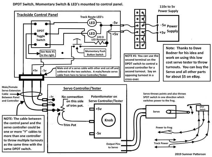
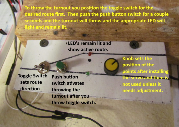
….. if you need the throw to be different at times then using a trim resistor might work better and they are less than 10 cents in quantity on eBay. I shown how to do this above. This gives you better control over the total throw. Switch the toggle one way and push the push button switch and adjust the knob on the controller. Switch the toggle the other way and push the push button switch and adjust the trim resistor for the other side of the throw.
The other nice thing about the schematic above is that on the track side control panel you have the push button switch, toggle switch and two LED's mounted to the track plan on the control panel. You use a servo extension cable to go from there to the Servo Controller/Tester that can be located out of the way but where you can use it to adjust the throw and tension on the turnout points initially and later if needed. Another cable goes from it to the servo at the turnout. The Servo Controller/Tester gets it power via the cable from the control panel with cuts down on wiring and lets you use commonly available servo extension cable which don't cost much.
NOTE: I will have more pictures of this setup later. I have tested it though.
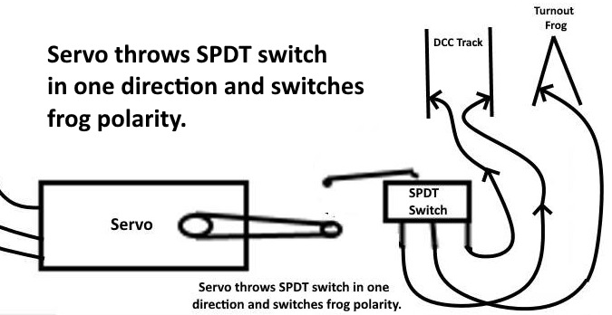
NOTE: If the turnout is not thrown in the correct direction to match the LED and route you can move the wire on the DPDT switch to the other end of the switch and that will reverse which way the turnout is thrown when the toggle switch is thrown.
The servo also contacts the SPDT limit switch which will then power the frog with the correct polarity.
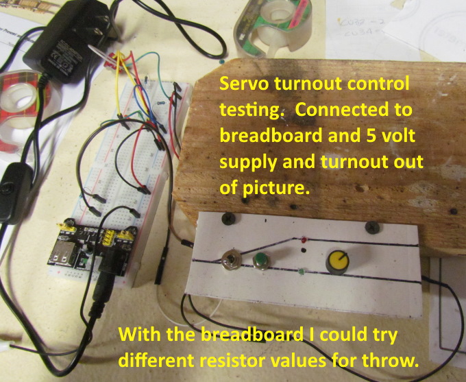
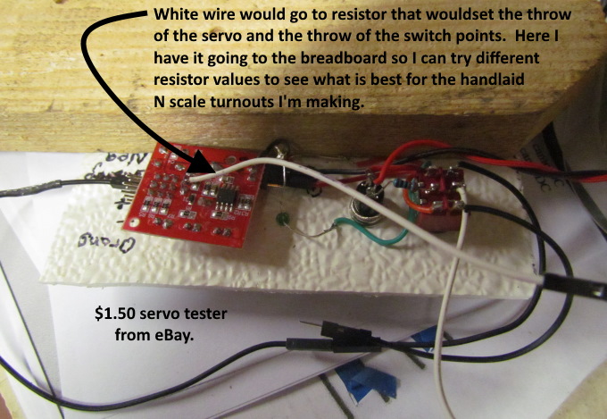
I tested the circuit and the servo as shown above. I had it connected to a breadboard that has a 5 volt supply on it.
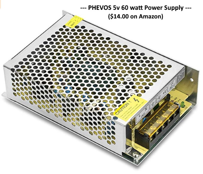
On the layout I'll use the 5 volt power supply I bought, shown above, to power the turnouts. You can find these on Amazon and other places for about $12.00. Other than the LED's that show the active route the servo controllers are only power when you throw the turnout so the power supply doesn't have a large load on it.
The small test panel I made is shown above.
Instead of having fixed resistor or trim resistor soldered to it I ran the wires for that circuit over to the breadboard so that I could quickly try different resistor values or a Pot wired into the circuit there. The final ones will probably use a trip Pot next to the knob that controls the inexpensive servo tester/controller. It will be exposed on the face so that it can be adjusted as required.
You could also use the same control for a servo connected to the turnout in a different manner or one used for a different purpose where you wanted to control the amount the servo rotates.
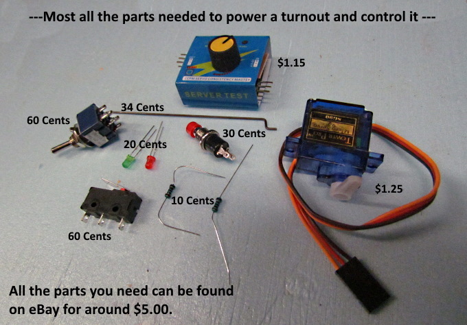
For about $5.00 you can get all the parts needed to throw the turnout and control it along with some wiring and fabrication on your part and that actually goes pretty fast once you have done a couple.
If you make your turnouts from scratch you will only have about $10 in a completed powered turnout. Quite a savings!
=========================================
...........................On..............e..........Next Page If There Is One