.................................. Return to Sumner's Home Page....
Return to N Scale RR Main Menu.............. Return to Trackwork Menu
=========================================
..............Previous Page..............................Next Page If There Is One
=========================================
….--- N Scale Code 55 3-Way Turnout Assembly Tips --- Servo for Turnout Control ---
=========================================
NOTE: This page is long but I feel it can save you time and frustration in building a 3-Way turnout.
After building a couple of 3-Way turnouts using the instructions FastTracks has ( HERE ) I started to make a few changes in the way I built the turnouts and things went somewhat easier but these are still not near as easy to build as say a #6 right or left hand turnout. I'd for sure recommend building something like those first to get the soldering and such down.
Before trying a 3-Way download FastTracks instructions and read them as they are a big help. They show building a 3-Way turnout using one of their fixtures which I don't have. The fixture for sure would make things easier and I still might buy one. I did buy their N code 55 fixture for a double crossover and have used it to build about 30 #6 turnouts so far and it works great. It costs a little more than the fixture for #6 turnouts but besides letting you build a single or double crossover you can also build #6 left hand and right hand turnouts and I think a 19 degree crossing with it. I'd also highly recommend buying the PointForm and StockAid tools along with that fixture. I used those PointForm and StockAid tools to also build the 3 Way turnouts, as the 3-Way also has two #6 frogs and the tools also work for the stock rails and the points that you need to build.
Also go back and read the page before this one if you haven't yet ( HERE ).
So what follows shows how I deviated some from FastTrack's instructions. These changes helped me in building more 3-Way turnouts.
I feel that building the point rail, from the point through the hinge and on to the guard rail portion as a single assembly and then soldering that to the ties is easier than doing the hinge part after soldering a point rail to the ties. On HO size turnouts where there is more room to solder I'd try staying with their instructions probably. When building the N scale turnouts things are so tight it is hard to get in there and make and solder the hinge area without messing up.
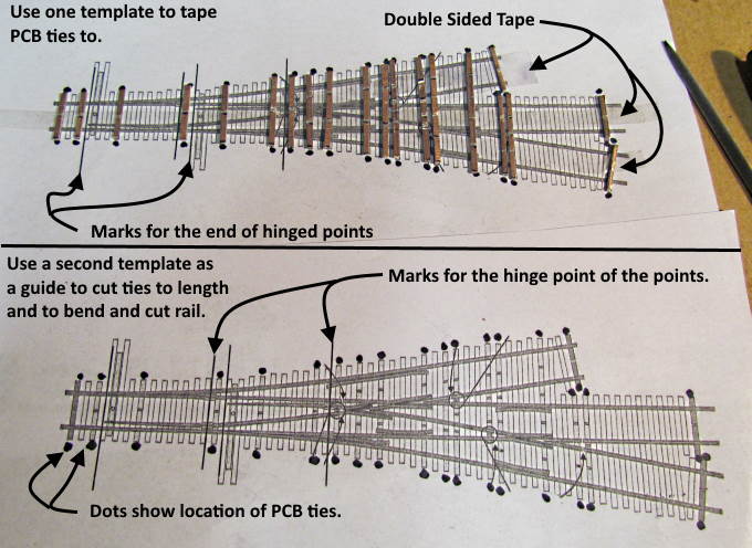
So on to the steps I take.....
I generally make my own PCB ties but you can also order them from FastTracks. I get my code 55 rail and individual ties from them.
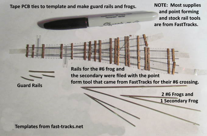
I make up the points usually in a batch for 2-3 turnouts at the same time. Above I have already made up the guard rails using the template as a pattern for them. Lately I've been making them a little longer than what is shown on the template if that makes it easier to solder them in place or I feel they will perform better being a little longer.
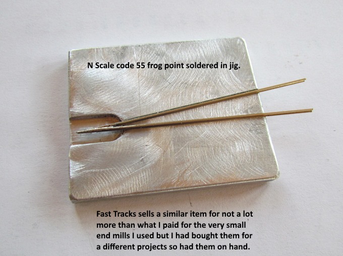
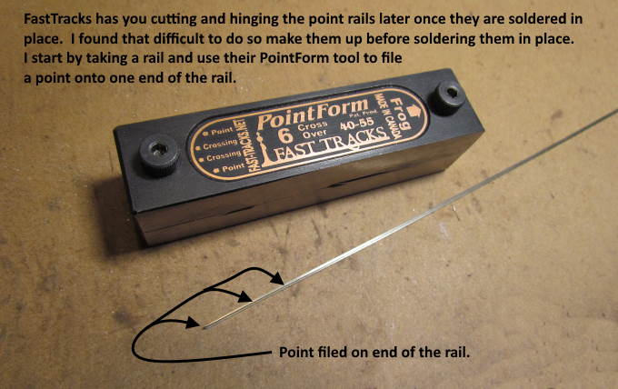
I first file the #6 frog points using the FastTracks PointForm tool I bought when I bought the #6 double crossover fixture. Then I solder them together with the jig I made show above. FastTracks also sells them or you could hold the rails in correct position for soldering them using double sided tape on top of the template.
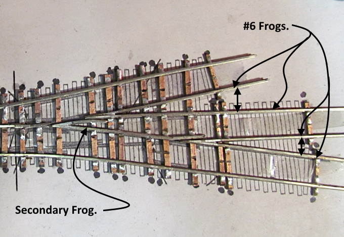
To make the secondary frog I use the PointForm tool that I bought with the #6 double crossover fixture since it also has a part where you can file the points to make the crossing in the double crossover. It is off by a couple degrees of what you want here but I've found that it is plenty close enough to make the secondary frog.
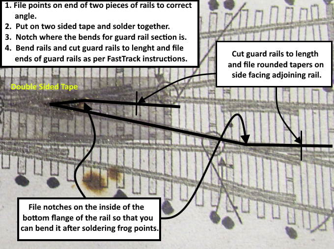
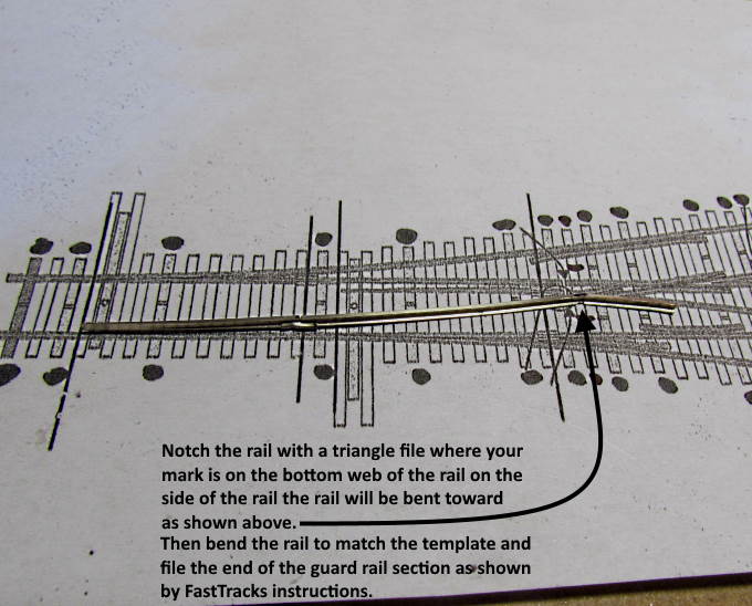
File the points using it or by another means and put the points on the double sided tape on the template and solder them together. Then make the notches in the bottom of the rail with a triangle file and make the bends so that the guard rail parts follow the template. Next cut those ends to length and file the ends as per the FastTrack's instructions with a rounded taper on the side facing the adjoining rail. This will help if a wheel hits the end of the guard rail and will direct the wheel in the right direction.
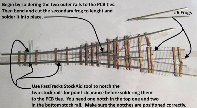
I make up the two outer stock rails and solder them in place on the PCB ties but first you have to notch them where the points will make contact with them. The bottom rail needs two notches and the top rail one. Make sure the notches are exactly where they need to be using another template to mark them before filing them with the StockAid tool or by another means.
The tool is invaluable for this if you are making a lot of turnouts and the one StockAid tool you can get from FastTracks will work with any turnout you make, so you only need to buy one.
I solder first the secondary frog in place and then the two #6 frogs in place. This secures all of the ties to rail and further holds them in place. Make sure to use a gauged truck and a NMRA track gauge to make sure the rails at this point are in gauge. Move them if they aren't and continue to do this constantly as you build the turnout. Don't wait until the turnout is done.
- - - - - - - - - - - - - - - - - - - - - - - - - - - - - - - - - - - - - - - - - - - - - - - - - - - - - - - - - - - - - - - - - -
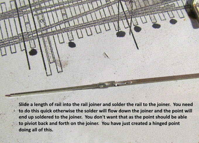
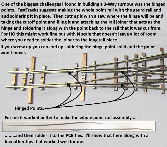
Now here is the main area where I deviate from the FastTrack instructions. They will suggest that you make one long point rail with the bent guard rail at the end and solder it in place. Then later you would cut the rail while it is soldered to the ties where the hinge point is with a saw. Then modify the point so you can secure a rail joiner to it. Next put the rail joiner onto the point rail you cut at the hinge point and crimp it in place with diagonal pliers. Next push it onto the rail it was cut from and solder the rail joiner in place.
That worked pretty well for me for some of the hinge locations but for some it was hard to get in there with a N scale turnout and solder the joiner to the main rail section. If you got too much solder or soldered for just a tad too long the solder would wick down the rail joiner and solder the point part solid so that it wouldn't hinge. Then you have a real mess to get it fixed.
I decided to do most of this work first without it being attached to the ties. This way if I got solder into the point/rail joiner section and soldered the point solid I could easily fix it. Also making the point, hinge (rail joiner) and rest of the rail with the bend and guard section in one piece I could solder it on in one step and not have to make the cut and hinge point later. It would be done.
Follow along as I explain how to do this....
Start by taking the PointForm tool and filing a point on the end of a length of rail.
.
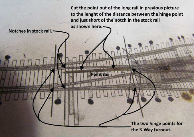
Put the rail with the point on it on the template and mark it accurately to the length from the hinge point to where it will touch the stock rail when thrown. Move it back from the end of the notch in the stock rail a tick when taking the measurement. I cut it a touch long and file the end square and clean the cut end up a bit so that it will slide into a rail joiner.
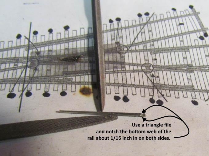
Next take a triangle file and notch it just inside the end like shown above.
Tool that will help at this point.
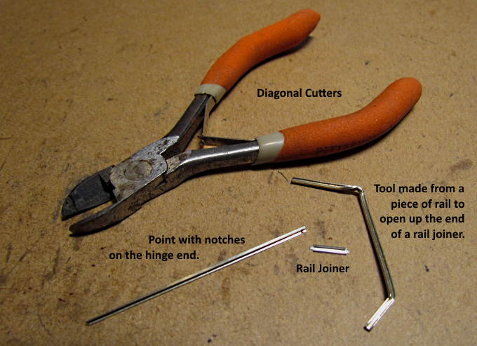
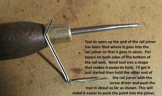
Open one end of the rail joiner so that it will slide onto the point rail as shown above.
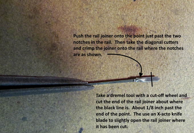
Crimp the joiner to the point rail with the diagonal cutters and cut some off the rail joiner where the black line is before preceding.
You can find a good FastTracks video on making hinged points ( HERE ) and I'd for sure watch it. We won't be building the hinged points with the rail soldered to the ties like shown. I feel what follows is an easier way with a N turnout but the video will go into how the hinge part is made which is good info and you can consider which way you want to make the hinges for your turnout.
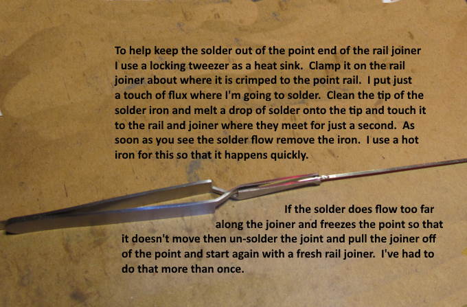
Carefully solder the joiner to a length of rail being careful not to let the solder joint extend into the point rail end of the joiner.
Above some ideas on making this solder joint work and keeping the hinge action in place. If you solder the point rail end so that it doesn't hinge then start over. Much easier to do this with none of this soldered to the ties.
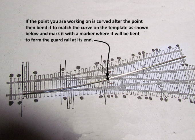
Making the point rail follow the template.
Finishing the guard rail end of the point rail off.
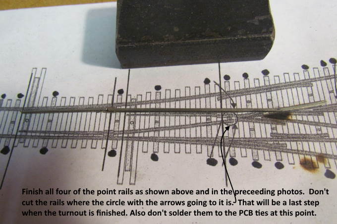
Make all four point rail assemblies before soldering any of them to the ties.
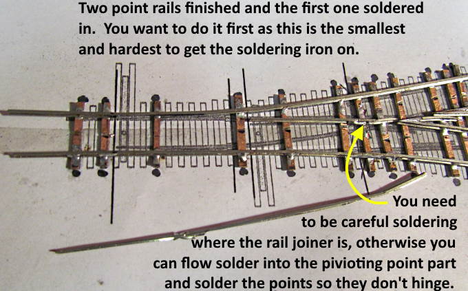
Solder the short upper one on first.
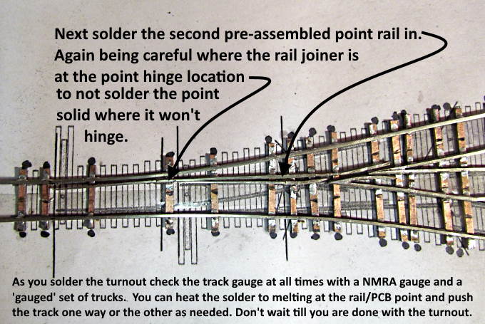
Followed by the longer upper one.
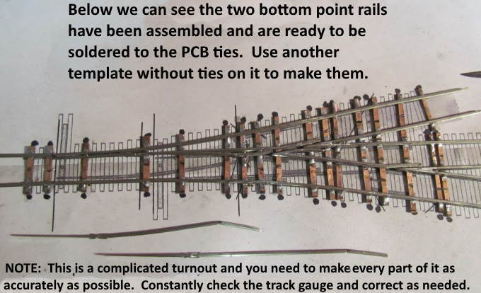
Make the two bottom point rail assemblies if you haven't already done so using another paper template with no ties on it.
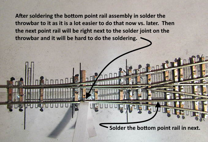
Solder in the long-rear point rail in next.
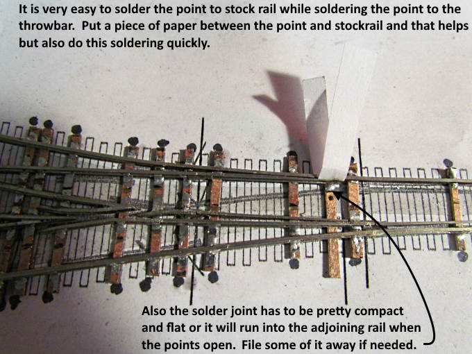
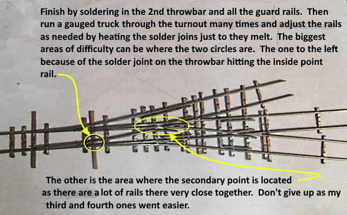
Solder points to throwbar for this turnout on before preceding. Use the paper to avoid soldering the throwbar/point to the stock rail by accident. This is a critical area of the turnout as the soldered point on the throwbar is very close to the rail next to it.
If the solder joint is large when the switch is thrown the point and solder joint will hit the adjoining rail and the points won't throw far enough. Keep the solder joint small and notch the bottom of the adjoining rail for clearance here (See the next picture).
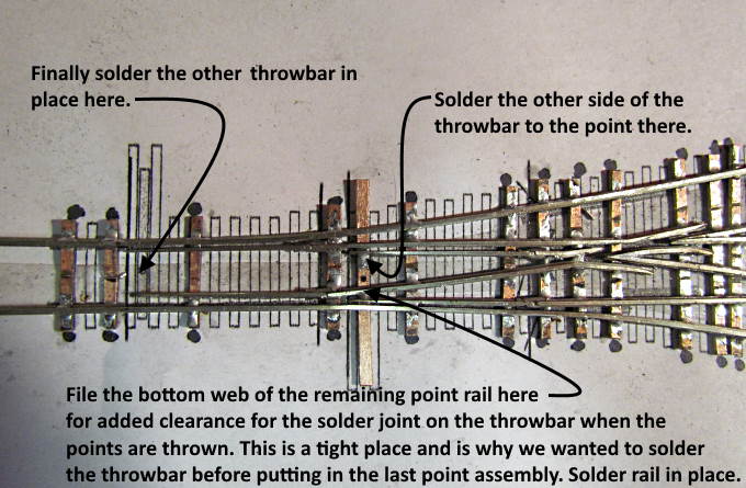
Solder the other side of the throwbar to the point on that side and then solder in the final point rail assembly. I'd recommend notching it a little where the previous point is soldered to the throwbar for clearance sake.
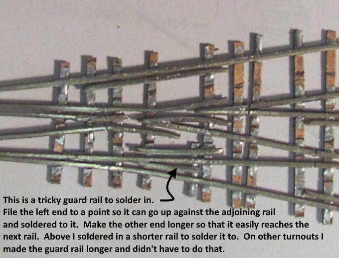
You are almost done. Solder the throwbar to the other set of points then solder in the guard rails. Most are easy but the one above is a little tricky.
You are done building the turnout. Congrats and you can move onto ..
… gluing ties to it with instructions ( HERE ).
The first one of these took me a long time but the fourth and fifth ones went considerably faster so stick with it. Also consider the FastTrack fixture as an option.
=========================================
...........................On..............e..........Next Page If There Is One