.................................. Return to Sumner's Home Page....
Return to N Scale RR Main Menu........ Return to Servo Control Menu
=========================================
..............Turnout Switch Box..............................Servo Controller/Servo Tester
=========================================
…..........--- Servo Controller and 3D Printed Bracket ---
…..............--- 3D print files can be found ( HERE ). ---
=========================================
Important Update (03-31-23): I've made a change to the wiring of the servo controller.
Occasionally I was getting erratic behavior when using the controller to adjust the throw of the servo. Checking the trimmer pot and sometimes the main pot that is on the controller itself I found that they were not reading from 0 to 10K ohms reliably. I'd change the trimmer pot out or the controller board and things would be normally again. I put it off to poor quality of the cheap parts. After it happened a few more times I checked things out better. I finally realized that with both pots turned fully in the clockwise direction there was the full 5 volts flowing through the trimmer pot resulting in excessive current also flowing through the pot and damaging it as it is only rated to 1/10 of a watt. Didn't damage all of them but did damage some.
If you didn't have both pots turned fully then the current was reduced and the pot seemed to not fail. Usually you don't end up with them both full on as the throw is too much so once set the throw the pot was OK as the current was then lower.
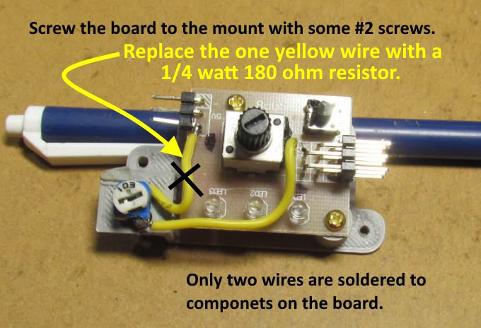
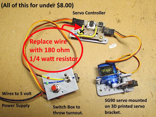
The solution that seems to be working fine is a change to the wiring as shown above. I replaced the one wire from the pot to the 3 prong plug to a ¼ watt 180 ohm resistor. It limits what the maximum current can be through the pot to about .020 ma resulting in 1/10 watt. I've changed a large number of the controllers over to the resistor and have had no problems with any of them. The resistor can lower the throw by just a touch but I still have plenty of throw. I was able to order 100 of the 180 ohm resistors from Amazon for about $6 so this is a very cheap upgrade to the wiring.
========== Be Sure to Read the Above =================
On this page we will build the servo controller. Not much to it, mount a trim pot and solder on two wires and it is ready to go. If you can't print the bracket shown it wouldn't take much to make something else up.
Above is the 3D printed bracket and the files can be found ( HERE ).
.
You can find a link for the servo controller in the parts list ( HERE ). By buying a larger quantity I was able to get them for less than $1.25. You can buy in smaller quantities for not a lot more.
Remove the knob and paper covering.
I just bend the solder tabs over to hold the trim pot to the bracket.
=========================================
Next up a change in the wiring....
NOTE: A number of the following pictures will show the initial wiring I presented. It can work if you are careful to not have the pots turned fully in the clockwise direction but it is easy to make that mistake when doing the initial adjustment of the servo. So I strongly recommend using the ¼ watt 180 ohm resistor in place of the wire from the trimmer pot to the out/in pins on the 3 pin connector for the servo cable as shown above.
NOTE: Above and on following pictures you will see where I “X” out the one wire and say to replace it with a resistor. This is an important upgrade that I strongly recommend doing.
A couple #2 screws hold the board to the bracket. I picked up 100 for under $5 on Ebay.
.
It is somewhat tricky getting the one wire soldered to the center lead of the larger pot. Tinning both and ….
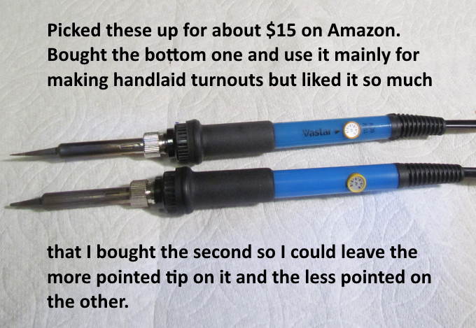
… a fine tip iron helps. You could also solder the wire to the under side of the board where the pot is soldered on. I like the approach above and it isn't that hard once you have done it a couple times.
Since we won't be using the two top row of pins on the header to the left I cut one pin off for more soldering clearance You can also see where I melted the small push-button switch housing a touch :-( . It survived. I then started cutting the top pins off coming in from the other side and that was pretty fast to do. Remember you only need the bottom row.
Instead of soldering to the middle pin on the top you....
…. can solder to the pin on the bottom. I like this method better now and it is faster to do. Strip the end of the wire so there is only about 1/8” of bare wire. Tin the end. Put a drop of solder on a hot iron (I run as hot as it will go). Hold the tinned wire on the center post and touch the iron and drop to both. It should flow in just a second. Pull the iron away and it should cool quickly and you are done. Once you do it a couple times you will find this to be fast and easy. I usually do this before attaching the circuit board to the mount and hold the circuit board firmly in place in my small vise I use for everything.
Above we see all the components needed for servo control minus the 5 volt power supply. I'll run a 5 volt buss around the layout and tap into it where needed for the switch box and the rest of the servo circuit.
It is important to plug the servo cables in properly as you can reverse them 180 deg. ( I found that it seems to survive this mistake). I put a black dot with a magic marker next to the pin where the signal wire is which is usually yellow or orange.
Start the servo controller setup procedure by turning both pots all the way clockwise so they are 'full on'.
The controller will be used to setup the servo for a proper throw of the points. One where you end up with pressure on the points but not too much. This has to be done as the servo has a far greater throw than what is needed or wanted.
It is best if you have it in a position where you can put something on the push-button switch as it has to be held down while you adjust the pots on the servo controller.
A test stand like the one above is a big help if you have many of these to do. You don't need the servo under a turnout at this point. You just need to see how far the control wire to the turnout is being thrown. The servo and switch box don't need to be the ones you use on the layout. One of each can be left on the test stand. You will only change out the servo controller.
Here are a couple more pictures of the test stand that I made in about twenty minutes. I should of made it earlier as it speeds up calibrating the controller.
.
.
.
I tried to write out the procedure on calibrating the servo controller but decided that a video would do a better job. Click ( HERE ) for the video or on the picture.
Once you have done it a couple time it is a 1 to 2 minute procedure and something anyone can do. No computer knowledge necessary ;-).
=========================================
…..............--- 3D print files can be found ( HERE ). ---
=========================================
...........................On..............e.........Servo Controller/Servo Tester