..................................
Return
to Sumner's Home Page....
Return
to N Scale RR Main Menu........ Return
to Servo Control Menu
=========================================
.......Soldering
Tools and Supplies I Use...............Option
to Reverse Servo Throw...................
=========================================
….......---
Turnout Control/Switch Box Wiring ---
=========================================
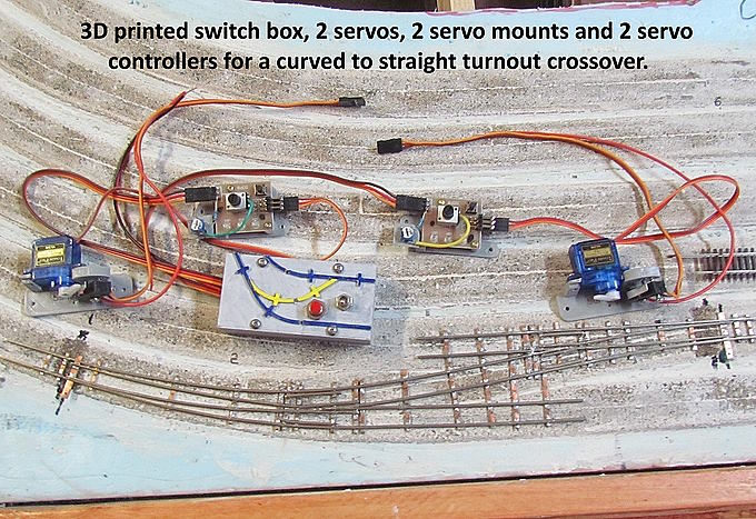
On
this page we will go into wiring the turnout control/switch box.
Again you could put the following in/on a control panel you built vs.
using the 3D printed box and tops.
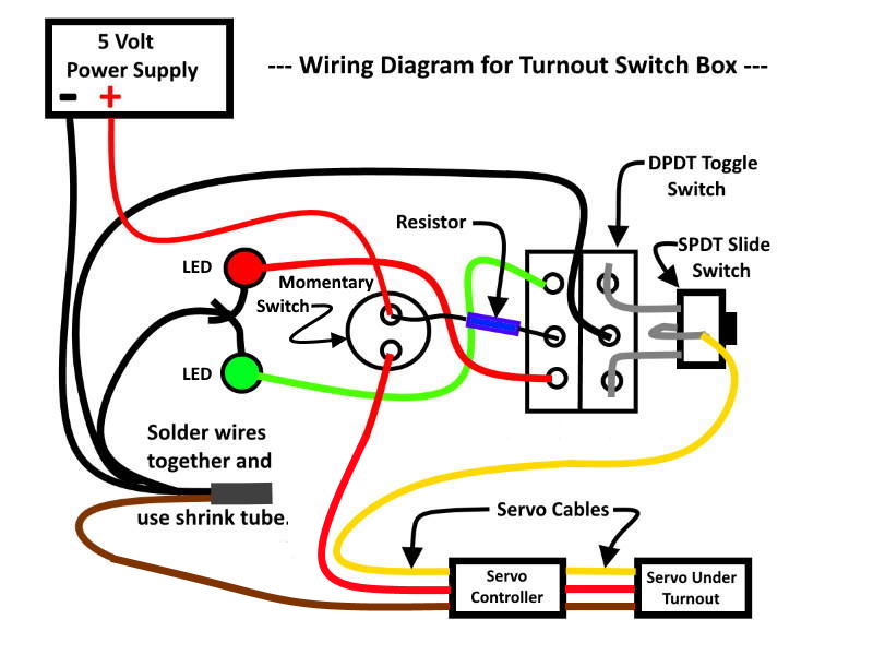
Above
is the wiring diagram for the turnout switch box. At the bottom right
you see boxes for the 'Servo Controller' and the 'Servo' that will be
used to throw the turnout. You use different lengths of servo cables
to connect the three items together. The cable comes in different
lengths and they can be daisy-chained together. Also the SPDT slide
switch is optional. To see if you want to use it or not go ( HERE
)
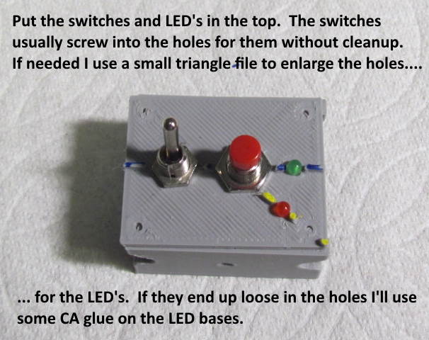
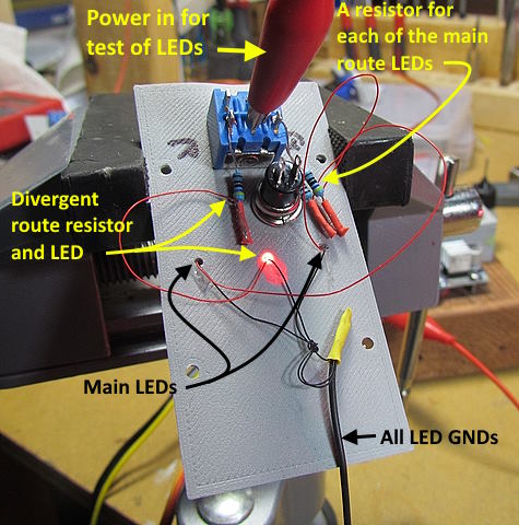
Now
we will start the actual wiring of the turnout control circuit. In
this case I'll use one of the 3D printed tops but this could be a
conventional control panel top also. In that case you might want to
do the wiring on a small dummy top with holes in it for the switches
and LED's and then move the completed wiring to the control panel.
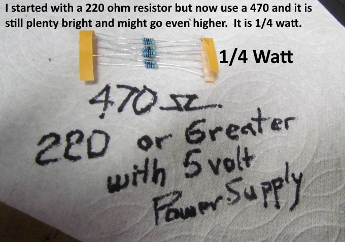
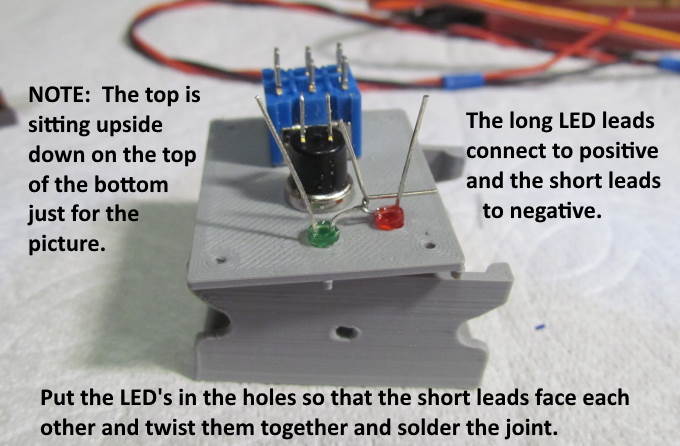
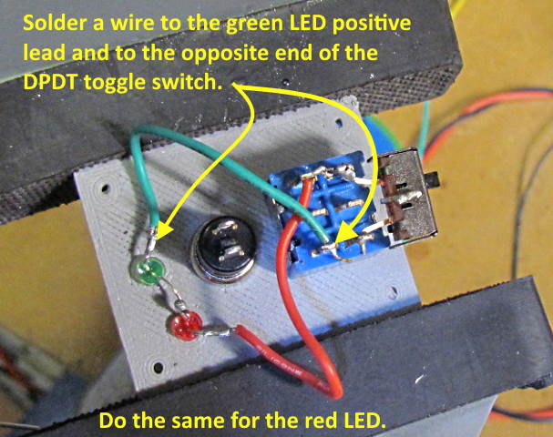
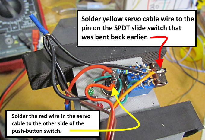
You
need a resistor in the circuit to protect the LED from burning out
even with the 5 volt power supply. You are safest using a 220 ohm
resistor or one with a greater value. The greater the value the
dimmer the LED will be. Try some different value resistors and see
which value you like the best, light intensity wise. At the moment
I've settled on 470 ohms but might still go higher at some point. The
red shows up brighter than the green but that might be good as I'm
using red for the divergent route and normally wouldn't want that
chosen in most cases as the normal route. You could use other colors
than red and green.
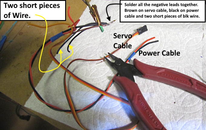
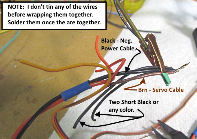
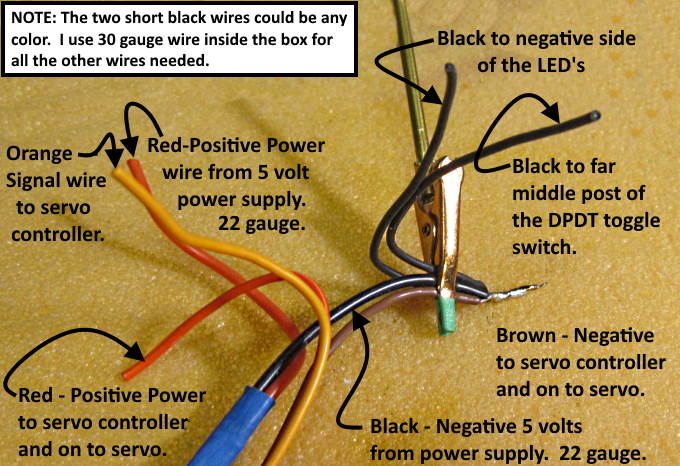
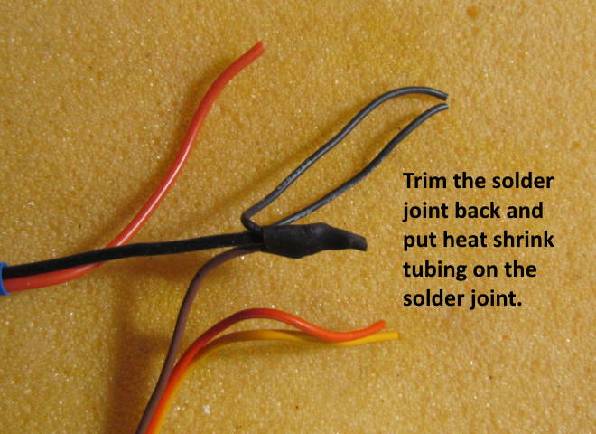
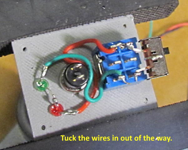
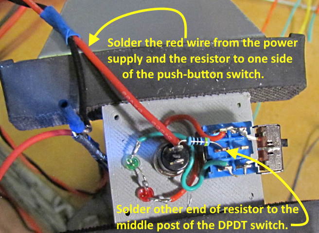
From
this point on the pictures should pretty much tell the story. If not
contact me at ( contact20 (at) 1fatgmc (dot) com ). The wiring might
seem a little complicated at first glance but once you have done a
couple of these it shouldn't take much over 15 minutes to doing one.
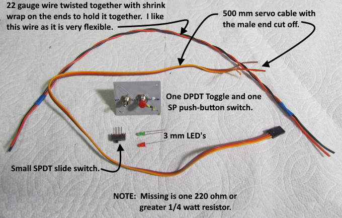
The under $8.00 cost for a servo, all of the parts shown here and for
the servo controller should make up for having to do a little work
;-). Turnout control from the control panel to the turnout for $8.00
or less is really a good deal.
.
.
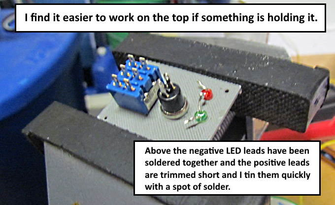
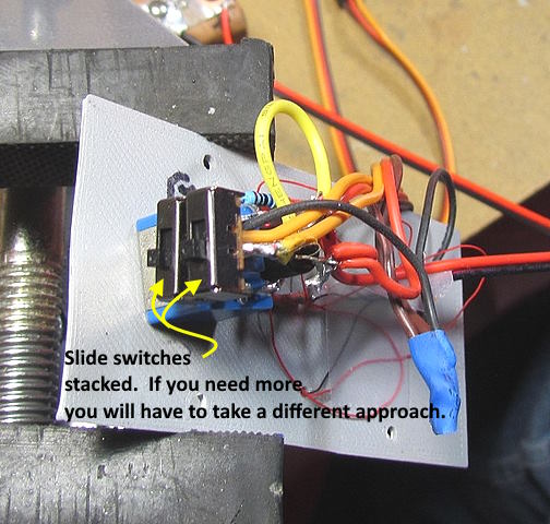
You
will find the wiring much easier if you are holding the top in a vise
or printed circuit board holder.
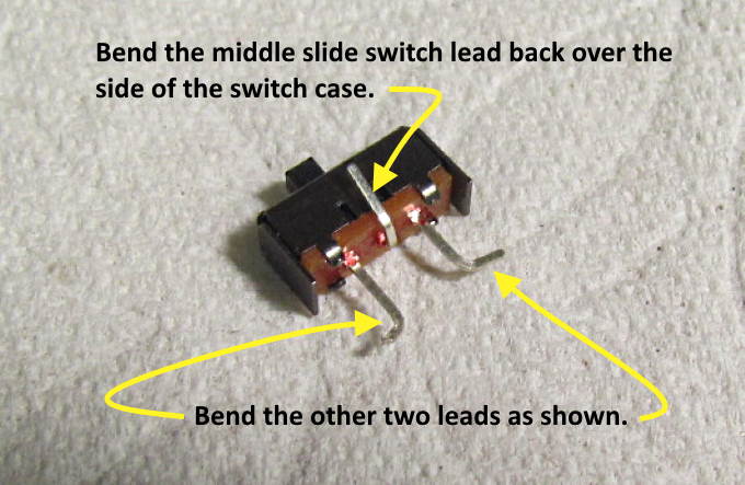
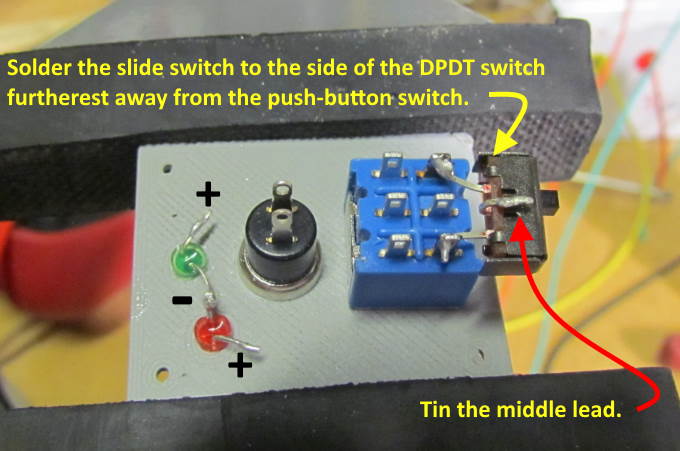
The
SPDT slide switch above is optional. To see if you want to use it or
not go ( HERE
)
.
.
.
.
.
.
.
.
.
===
Options to control more than one servo with one switch box ===
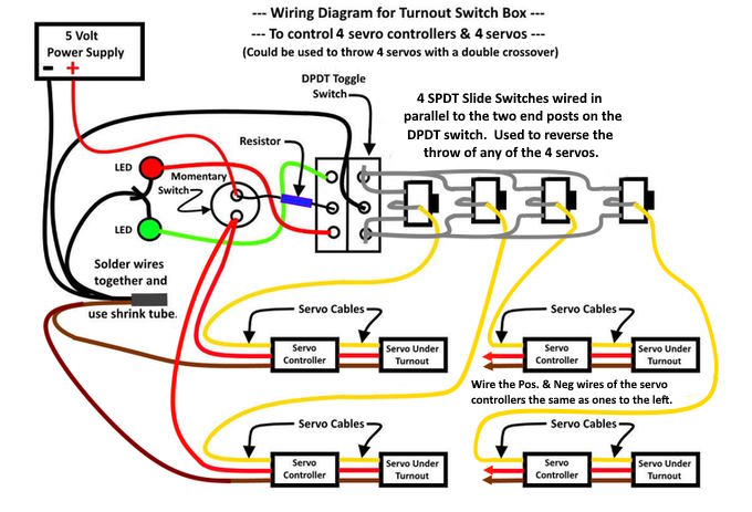
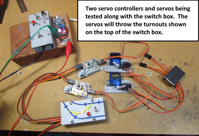
It
is easy to control more that one servo with a single switch box using
a switch-box as shown below along with the servo controller shown
after this page.
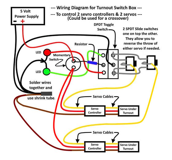
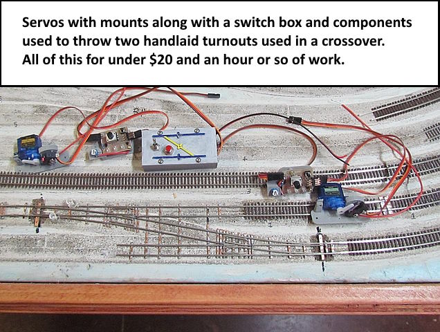
The
wiring diagram shows how to connect to a second servo controller that
is connected to a second servo. This is handy when it comes to
throwing more than one turnout from one switch. Nice for a crossover
or maybe a route change through a couple turnouts. The next wiring
diagram shows how to add even more servos to those being controlled
by a single switch box.
.
I'll
get the print files up on my thingiverse.com account ( HERE
) for a switch box like above.
.
.
.
.
.
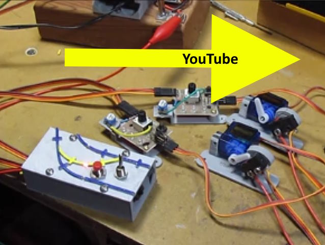
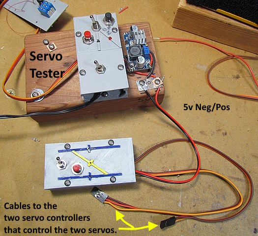
For
a video on testing the switch-box, servo controller and servos click
(
HERE ) or
on the image above.
For
more on the option to use or not use the slide switch connected to
the toggle switch go to the link below or move onto wiring the servo
controller. It only takes a couple minutes to do as there is only one
wire and one resistor that needs to be soldered. After than just
connect the cable from the switch box to the controller and a cable
from it to the servo and you are in business. To move onto the servo
controller click ( HERE
).
=========================================
...........................On..............e.........
Option
to Reverse Servo Throw