..................................
Return
to Sumner's Home Page....
Return
to N Scale RR Main Menu........ Return
to Servo Control Menu
=========================================
..............Previous
Page..............................Next
Page If There Is One
=========================================
…....---
Overview of Simple and Inexpensive Servo Control ---
=========================================
I've
been working on a way to control servos for turnouts and other uses
that is inexpensive and doesn't require using an Arduino or expensive
commercial servo controllers. If you know how to solder and have
access to a 3D printer or can find someone who does for under $8.00
you can control servos for your turnouts or other simple uses. If you
don't go the 3D printer route you can make your own servo bracket by
other means and you can still use everything else below to control
servos for turnouts or other times you need a servo controller for
simple applications.
You can't control a servo with a simple
on and off switch, you need a servo controller. Dave Bodnar came up
with the idea of using a servo tester as a means of servo control. If
you buy them in quantity you can find them for as little as $1.50
each. Add about another $4.00 to that for LED's, switches, a
resistor, servo cables and a little wire and you have not just a
servo controller but also a control box that can sit at the edge of
the layout and that is used to throw the turnout and show which route
is active.
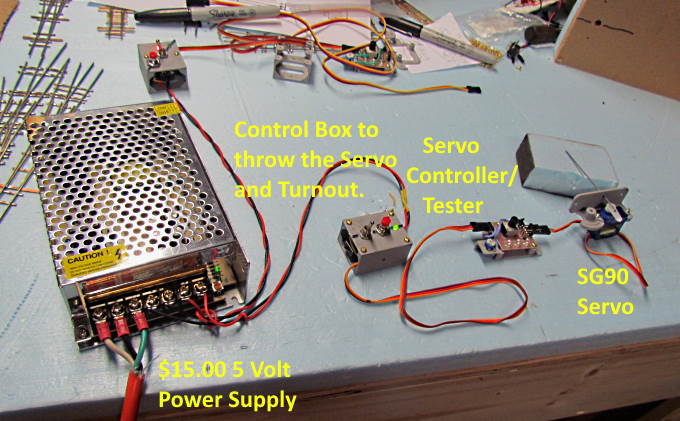
I
picked up a 5 volt power supply for $15.00 that will power about any
number of servos and controllers as they only draw current when a
turnout is thrown. You run two power wires from the power supply to
the control box. You could run a pair of wires around the layout from
the power supply and tap into them where needed.
From
the control box to the servo controller and on to the servo itself
you use inexpensive 3 wire servo cables that you can buy in different
lengths and daisy chain together if needed.
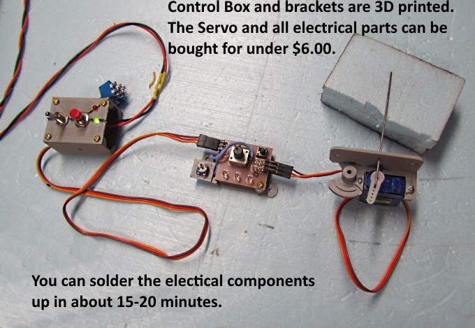
The
control box (3D printed) contains 3 switches (one not shown inside
the box), 2 LED's that show the chosen route and a resistor. On
Subsequent pages I'll post pictures of the wiring inside along with a
wiring diagram. The wiring is simple and you can wire one up in under
30 minutes once you have done a couple.
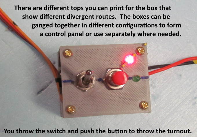
There are a number of
different tops you can print that show a left or right-hand turnout
facing different directions, curved turnouts and turnouts as you
would see them in a yard ladder. You can place the box wherever it is
needed or gang them together so as to represent the track plan. More
pictures on the following pages.
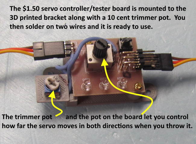
The
above board is mounted out of the way after the turnout and servo
have been installed and the throwbar travel set. You can use it to
adjust how far the servo throws the points in either direction. This
is helpful if you don't mount the servo exactly centered under the
turnout. Also the servos will throw the points way to far if you
don't have some means of controlling their throw. This way if you
need a little more or less pressure on the points it is easy to set
and can be adjusted easily in the future if needed. It will help for
the differences needed in throw depending on scale and layout
thickness under the turnout.
I took Dave's wiring example and
expanded on it a little by adding a second potentiometer (10 cent
trim pot) to the circuit. This addition is what allows you to adjust
the throw in both directions. Assembly consists of screwing the small
board above onto the 3D printed bracket and adding the trim pot to
the bracket and soldering on two wires. You could use some other
means to mount this if you don't have 3D printer access.
This
circuit is activated when you throw the toggle switch and push the
button on the control box at the edge of the layout. Another
advantage to this is that the servo is not powered all the time, only
when you throw the turnout. For this reason you don't need a large
power supply.
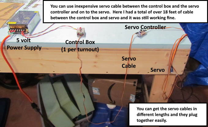
You
use different length servo cables between the components. Above I had
over 18 feet of cables daisy-chained together and it was still
working fine. The servo controller can go under the layout as you
only use it when you need to adjust the servo's throw on the points
so normally you would have a shorter cable than shown between the
control box and the servo controller. You can change the cable
lengths easily at any time as they plug into each other.
You
could use the components for other items on the layout where you
needed to move something with a servo and wanted to control the throw
and when it happens.
=========================================
WARNING:
One person bought Miuzei
SG90 servos on Amazon and they didn't work.
Went
90 degrees each time they were powered on. I would stay away from
them.
If
you find servos that don't work let me know.
=========================================
...........................On..............e.........Next
Page If There Is One