.................................. Return to Sumner's Home Page....
Return to N Scale RR Main Menu........ Return to Decoder Install Menu
=========================================
..............Previous Page..............................Next Page If There Is One
=========================================
........--- Minitrix FM H-12-44 Decoder Part 1 ---
I'm trying to get most of UP's locos from '40's into the early '70's. I couldn't find any FM H-10-44's but did find some Minitrix FM H-12-44's so bought them as they are suppose to be close to each other in looks. Then I found there is a pretty major difference in the cab's top at the back and found a nice FM H-10-44 shell on Shapeways so bought it and put it on an Atlas VO-1000 chassis with a decoder. You can find that info ( HERE ).
So what to do with the two non-UP FM H-12-44's I'd bought? I sold one to a person who needed parts and I decided to go ahead and put a decoder in the other just for the heck of it. I might see if I can print an extension I could add to the back of the cab to make it more like a FM H-10-44 even though it is shorter than the shell I bought.
.
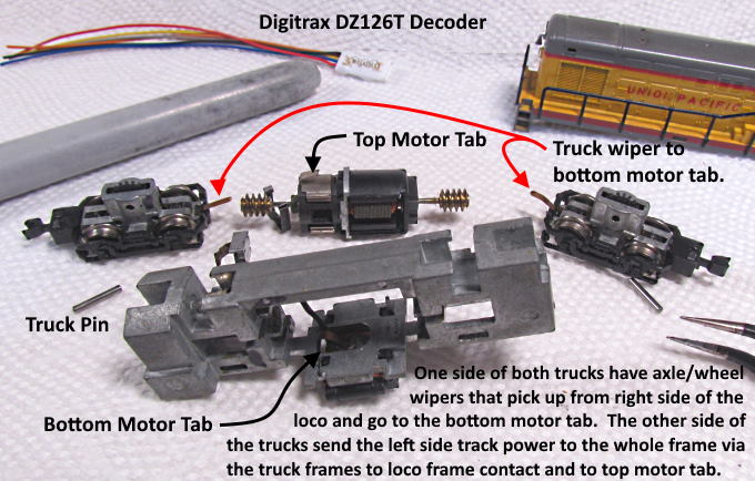
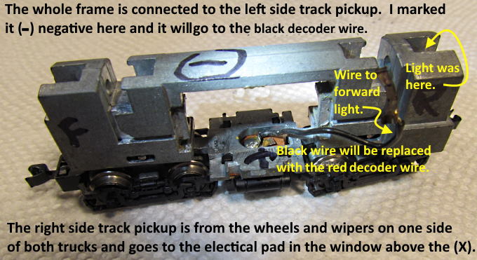
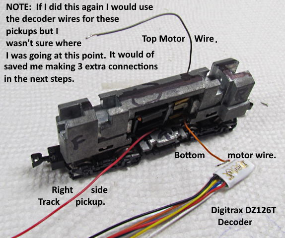
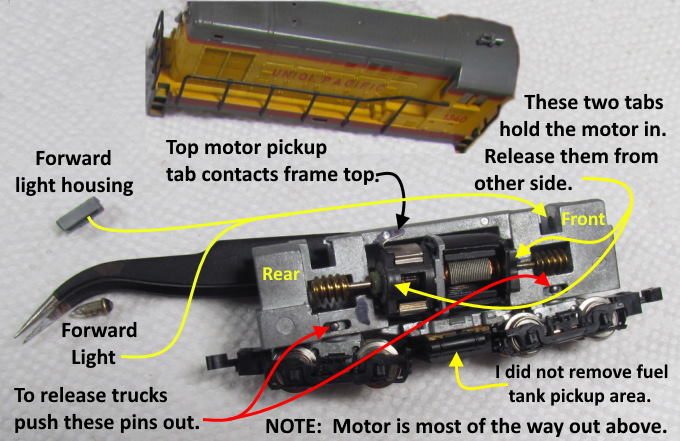
Above is a photo of the loco blown apart. It has a different pickup than I've seen before. Both trucks have axle/wheel wipers on the same side of the truck that conduct power from the track on the loco's right side to an electrical contact pad at the center bottom of the frame. That pad is insulated from the rest of the frame. There is a contact wiper on the pad that contacts the bottom motor cap. Also a wire from it goes to the only light, a forward light.
The wheels on the other side of the two trucks transmit track power on that side to the truck's frame and gear tower. There is a pin that holds the whole truck assembly in the frame and the frame rests on the pin and power is transmitted from the truck to the frame via that pin as far as I can tell. The end result is the whole frame except for the insulated pad at the bottom is connected to left side track current.
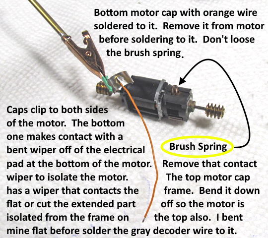
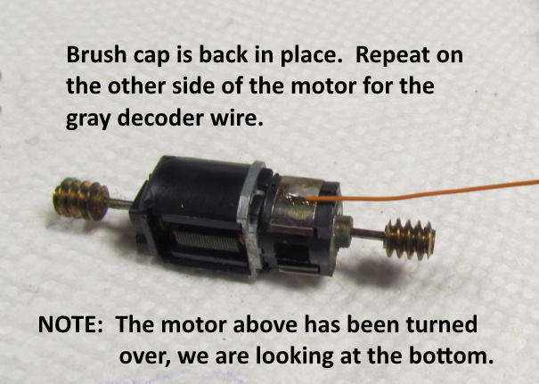
To insulate the motor from track power we have to remove the tab on the bottom insulated pad that contacts the bottom of the motor there. We also have to bend down or remove the bent tab at the top of the motor that contacts the frame at the top. Doing that insulates the motor and we can now attach the orange and gray wires to the motor as will be shown below.
.
.
.
.
.
.
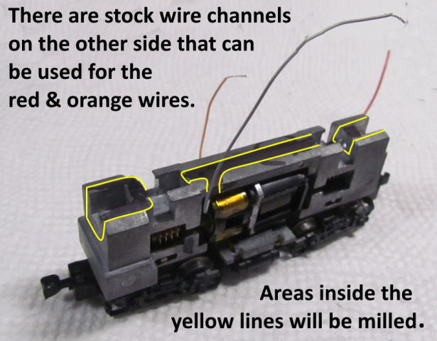
Next up is milling the frame and more wiring.
=========================================
...........................On..............e.........Next Page If There Is One