.................................. Return to Sumner's Home Page....
Return to N Scale RR Main Menu........ Return to HandCab Menu
=========================================
..............Previous Page..............................Next Page If There Is One
=========================================
….....................................--- HandCab WiFi Throttle – Part 6 ---
=========================================
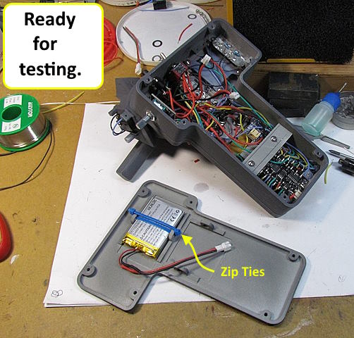
Battery Options & Charging Options:
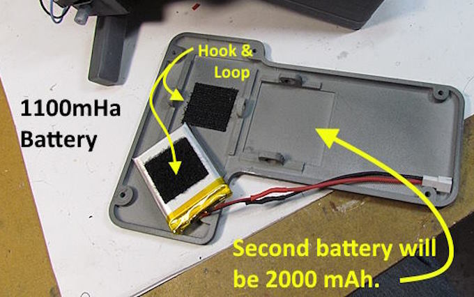
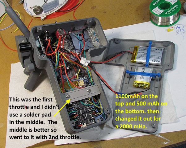
The throttle is going to need a minimum of one battery for operation. I personally like having a second battery that I can switch to if needed. The batteries are that expensive and another couple switches aren't either. Also you can charge the battery with the ESP32 as it has a charging circuit (I don't know how good that circuit is). I've added a $6 Adafruit 'true' 3 stage charger to the design and proved a port in the case on the side to mount it inside. If you choose to charge with the ESP32 I would still add an On/Off switch between it and the battery so that there is no battery drain even if the ESP32 is in 'Sleep' mode.
Next are some different wiring options:
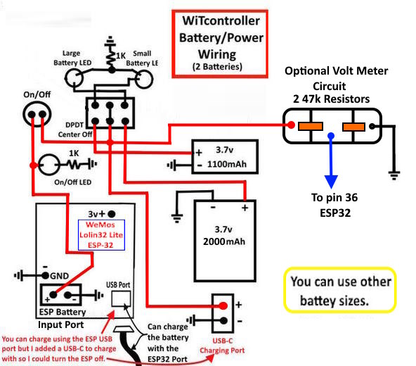
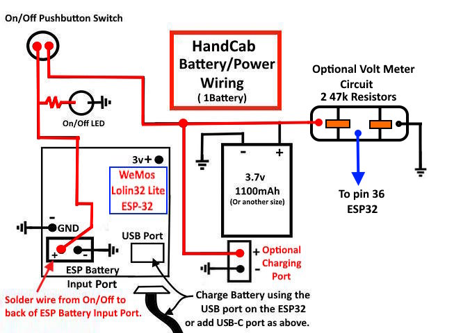
Above is the wiring diagram for one battery with an On/Off switch between it and the battery. Also the option to add a $6.00 3 stage charging board so you can charge with the ESP32 off. There is also an optional On/Off indicator LED.
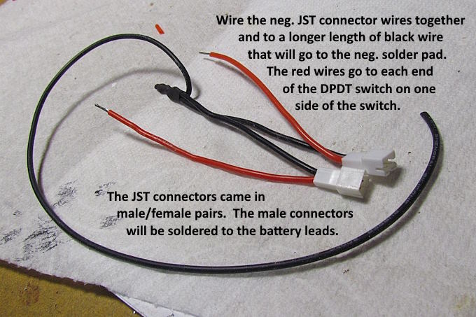
Above is the wiring diagram for two batteries with an On/Off switch between them and the battery. A DPDT center off toggle switch has been added along with indicator LEDs. The switch allows a center off or the choice to power the ESP32 from either battery and is also use to direct charging to the appropriate battery.
Previously in the build we showed briefly the option to add a $6.00 3 stage charging board so you can charge with the ESP32 off.
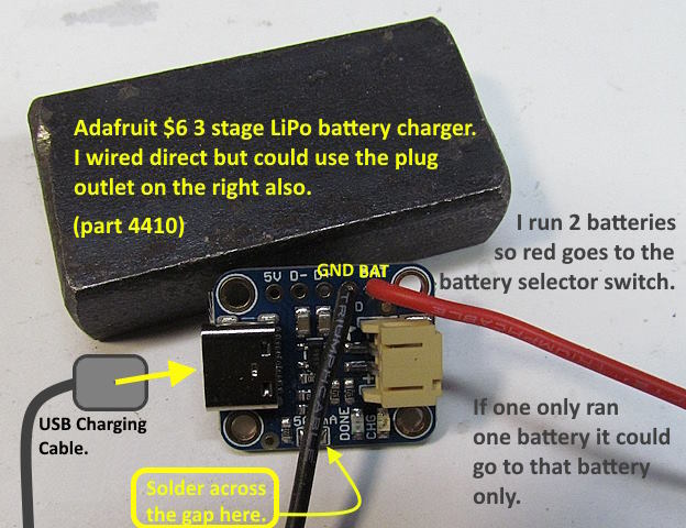
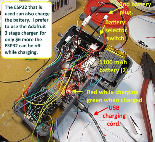
The WEMOS Lolin32 Lite ESP32 is capable of charging the battery/batteries but I like using the Adafruit 3 stage LiPo battery charger. It only cost $6 and is available from Adafruit or DigiKey. It comes setup as a 100mA charger but if your battery is over 500mAh you can solder across the 2 part pad at the bottom and it will charge at 500 mA per hour. Since both of the batteries I'll use are quite a bit over 500mAh I solder across the gap for the higher charging rate.
I can't find out much about the Lolin32 Lite's battery charging circuit but don't imagine it is as good at the Adafruit one. Also to use it the ESP32 has to be connected to a USB charging (5v) cord and the ESP32 itself is turned on while charging. I like the fact that for a few dollars more using their charger the ESP32 can be off except when you are using the throttle.
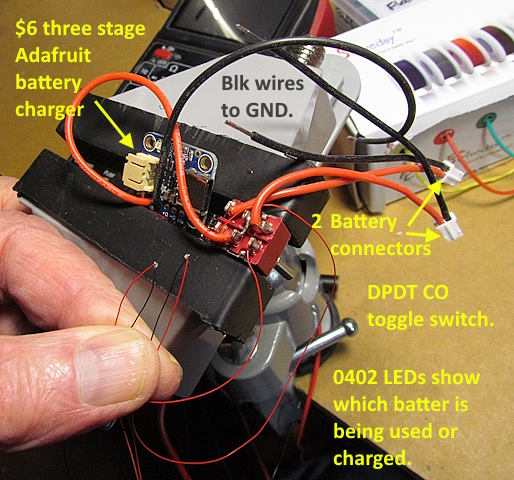
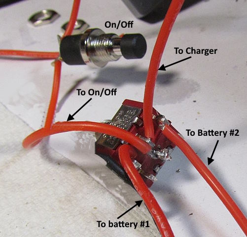
Above is the charging circuit. Red wire from Adafruit charger to middle two posts of the DPDT center/off switch. One set of outer poles on the toggle switch controls which battery is being used or charged. The other set goes to two 0402 LEDs that show which battery is in use.
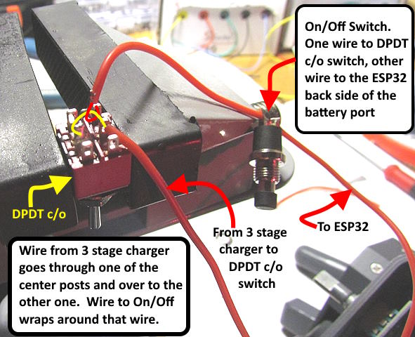
You will also run a wire from the two center posts to the On/Off switch that will be located next to this toggle switch. I strip the wire from the charger back a ways, and run it through one of the center posts and then over to the other one with a small loop between them. You want the two center posts tied together. I then wrap the wire going to the On/Off switch around the loop and solder that wire and the wire at the posts.
.
.
.
.
.
.
.
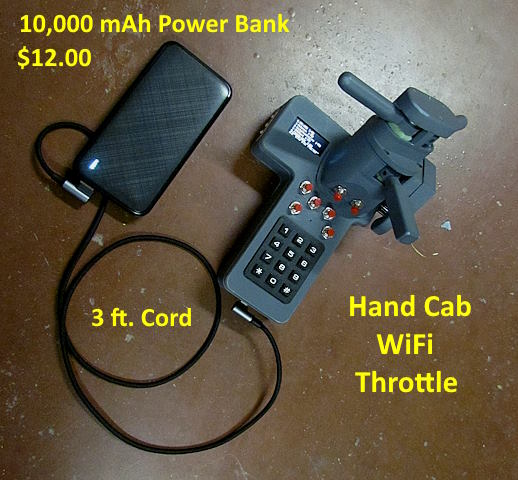
If you have really long operating sessions an external battery pack like the one shown above might be a solution for you. I've experimented with it a little and found it works fine if you leave the top battery toggle switch off and plug into the USB port on the ESP32 (not the 'charging port' on the side but that might work also.
Next.....
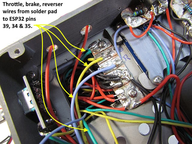
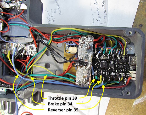
….. solder the wires for the throttle, brake and reverser from the solder pad under the control stand ….
….. to the ESP32.
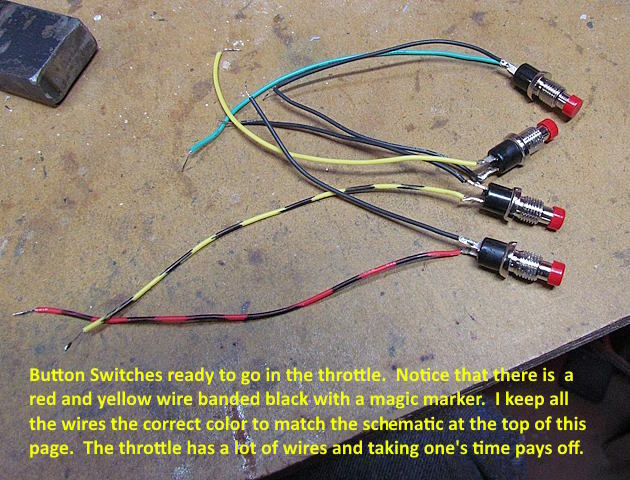
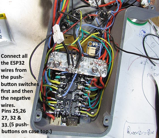
Next the 5 pushbutton switches that are on the top of the case are wired and installed.
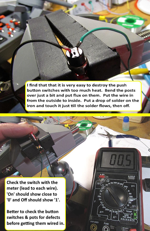
I've found that if you overheat these button switches while soldering the leads on they likely won't work or won't work reliably. If the plastic at one of the posts gets hot and the post can move around you might have to throw the switch away.
I tin the wire, put some liquid flux I like on the post, slide the wire in, have the tip of my iron clean and put a dab of solder on it. Have my $15 60 watt iron as hot as it can go and quickly dab the iron/solder on the post and wire. You should see the solder flow almost instantly. Remove the iron after it is on the solder joint for less than 2 seconds. As soon as you see the solder flow remove the iron.
This is typical of how to solder most of the wiring in the throttle. I have my iron on full hot (iron setting says 450c – not sure if it is). I clean the tip between almost every solder joint with the sponge or tip cleaner or both, just takes a second. Flux, hot iron, watching for the solder to flow and getting on and off quickly is key to not melting wiring here or wiring to your track.
More on the $15 irons (love them) and the flux I use and other soldering tips ( HERE ). You don't need a high dollar soldering station to have success soldering but doing it will make it easier over time.
.
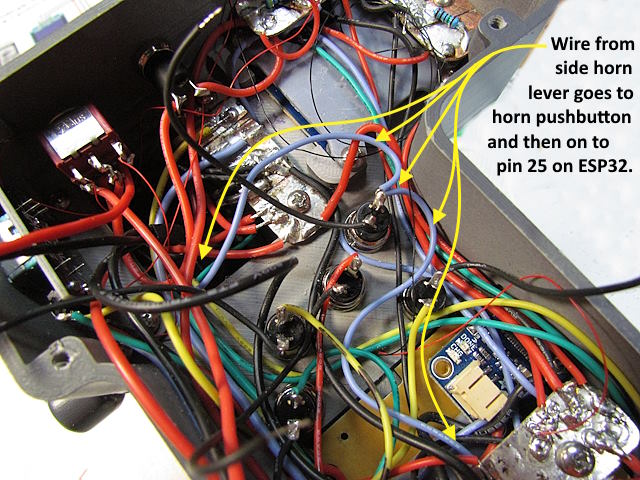
Put the 5 button switches in the case top along with their nuts. Solder the wire from the horn lever on the side (blue) to the side of button switch (B2) that has the wire that will go to the ESP32 pin 25.
Use the schematic to help wire all of the pushbutton switch wires to the ESP32 (you have been following the color code, right?)
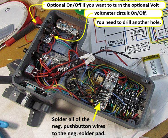
After soldering the pushbutton switches neg. wires to the neg. solder pad it is time to ….
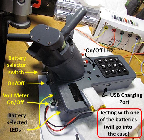
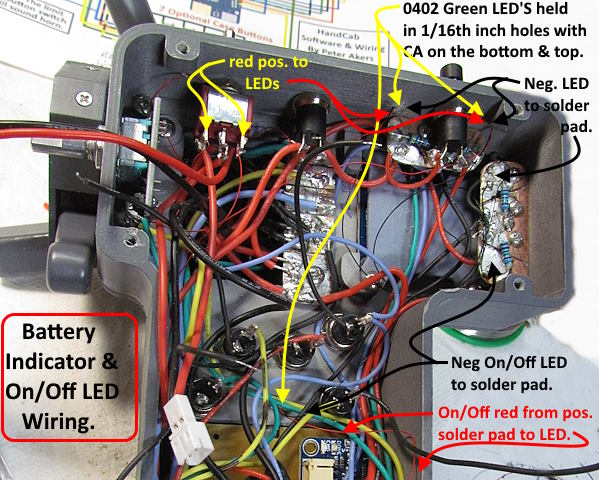
… put the battery indicator and On/Off LEDs in place and wire them. These are small items with small wires. I cut the wires a little shorter and bare the wire with an Exacto knife. I push them through the 1/16” (.0625”) holes till then come out on the top. The push/pull them back until they are just below the surface of the top of the case. Then hit them with very little CA and some CA activator to fix them in place. The CA on the top acts like a lens and the LEDs light up real nice. I used 1.5k resistors on this throttle and they are still plenty bright.
The positive (red) LED wires for the battery indicator LEDs go to the posts on the DPDT switch that selects the batteries. The positive LED wire for the On/Off goes to the positive solder pad. Both neg. wires for the 2 battery indicator LEDs go to the same side of the PCB with the 1.5k resistor on one side. One resistor is fine for both as only one is on at a time. The neg. LED wire for the On/Off LED goes to the other side of the same PCB.
For the whole build of this throttle go ( HERE ).
=========================================
...........................On..............e.........Next Page If There Is One