.................................. Return to Sumner's Home Page....
Return to N Scale RR Main Menu........ Return to HandCab Menu
=========================================
..............Previous Page..............................Next Page If There Is One
=========================================
….....................................--- HandCab WiFi Throttle – Part 6 ---
=========================================
Lots of wiring ......
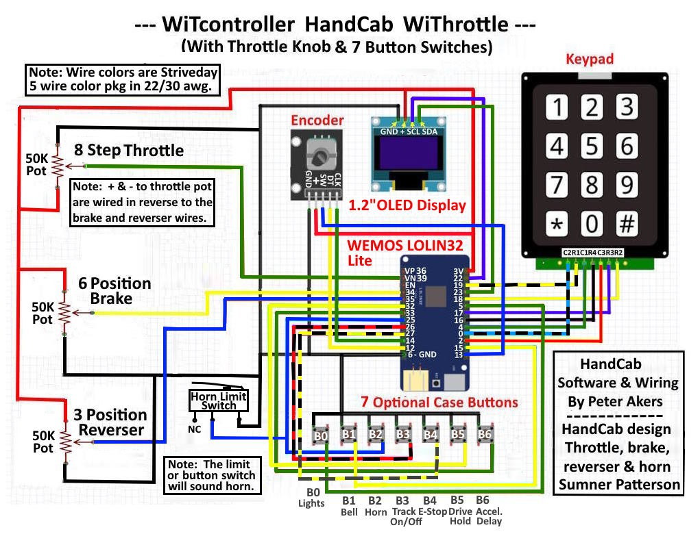
I buy the Striveday 5 color wire packs (box with wire holes) in 22 and 30 gauge for wiring. Most all of this wiring is the 30 gauge. Used it on the other throttles with not problems so hope that holds true. A couple more colors would help on distinguishing wires during the build. To make up for that I take the magic marker and band some of the red, blue and yellow wires as shown above. I'll try to stay true to the colors shown above during the build and would recommend that you do the same if you build the throttle.
One can remap any of the buttons to different functions except B2 (horn). That button is connected to the horn lever on the right side of the control stalk (not shown above). All of the other buttons could be remapped to a different function.
Also all the keys on the keypad can be mapped to functions. For example if you have a sound decoder that has multiple functions B5 could be mapped to the coupler sound and one of the keypad keys, say #1, could be mapped to Drive-Hold.
Time to start attaching wires to the two solder pads.
Sorry that I haven't shown the horn lever yet but wanted to show the limit switch that it contacts to sound the horn.
The blue signal wire from the limit switch is soldered to one post of the B2 button switch (second horn switch). The signal wire to pin 25 of the ESP32 is also attached to the same post. Pushing the button switch or activating the horn lever on the control stalk will sound the horn.
When you install the pots in the control stalk you want them positioned so that when the lever moves from one stop to the other stop it is operating roughly in the center of the pots range. The pot can rotate about 270 degrees but the throttle, brake and reverser levers only have about 120 degs of rotation. This is OK. Follow the instructions above and remember it doesn't have to be exact where it is. You only want to make sure that when a lever hits at stop that the pot isn't also at the end of its range in that direction. In other words make sure the pot isn't stopping the lever going in one direction or the other.
.
.
I've found that if you overheat these button switches while soldering the leads on they likely won't work or won't work reliably. If the plastic at one of the posts gets hot and the post can move around you might have to throw the switch away.
I tin the wire, put some liquid flux I like on the post, slide the wire in, have the tip of my iron clean and put a dab of solder on it. Have my $15 60 watt iron as hot as it can go and quickly dab the iron/solder on the post and wire. You should see the solder flow almost instantly. Remove the iron after it is on the solder joint for less than 2 seconds. As soon as you see the solder flow remove the iron.
This is typical of how to solder most of the wiring in the throttle. I have my iron on full hot (iron setting says 450c – not sure if it is). I clean the tip between almost every solder joint with the sponge or tip cleaner or both, just takes a second. Flux, hot iron, watching for the solder to flow and getting on and off quickly is key to not melting wiring here or wiring to your track.
More on the $15 irons (love them) and the flux I use and other soldering tips ( HERE ). You don't need a high dollar soldering station to have success soldering but doing it will make it easier over time.
.
.
To be Continued …...
For the whole build of this throttle go ( HERE ).
=========================================
...........................On..............e.........Next Page If There Is One