.......................................Endeavour Index Page..............Electrical Mods Index Page
....................................................Previous
Page.............................
Next
Page If There Is One
==================================================================
..................................................--- Helm Navigation Station ---
...................................................................................--- Part II ---
==================================================================
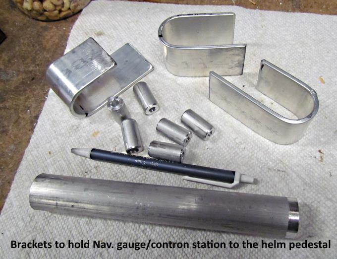
Next up was making pieces to mount the panel to the helm pedestal.
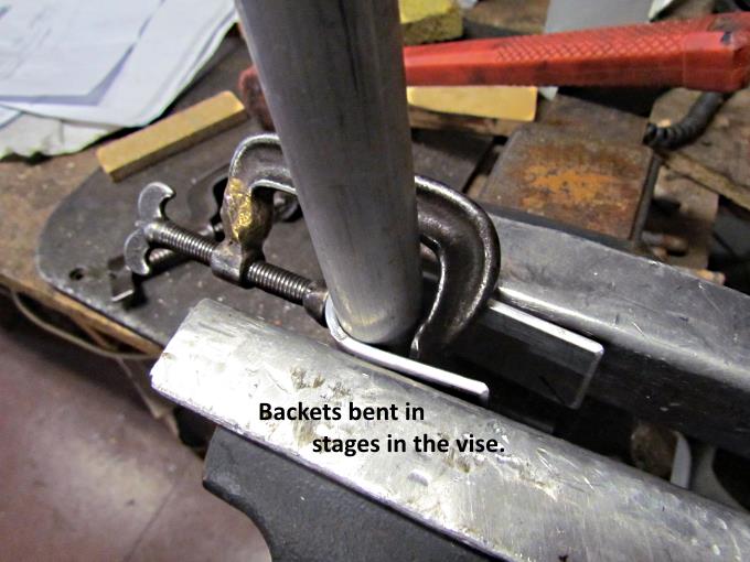
I made the brackets similar to others I had made in the past.
The SS tubing at the helm is 1" O.D. so I took a piece of 1" round stock and bent the brackets around them and ...
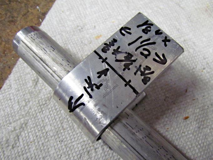
... cut them to the proper length.
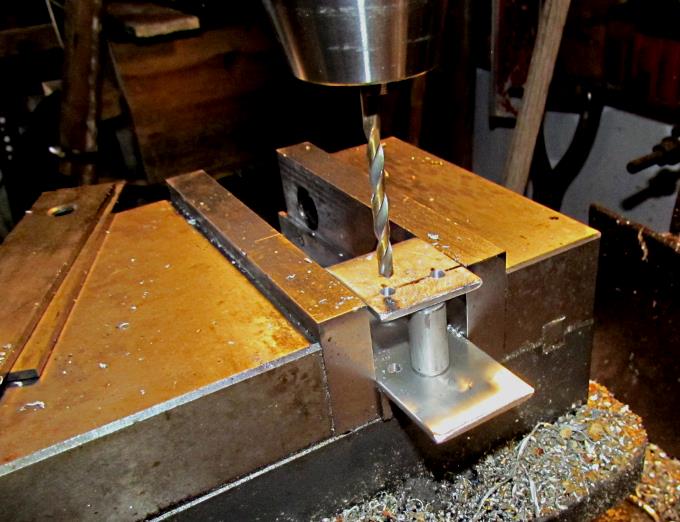
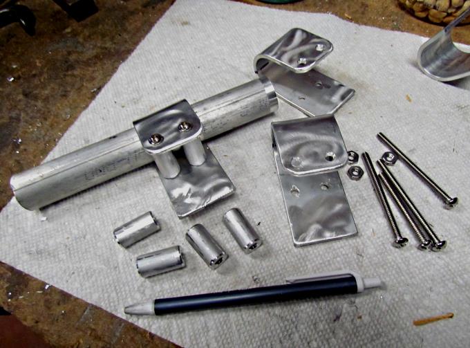
Next holes will drilled in the brackets. The standoff shown in the picture as also made along with others and they are slightly shorter than 1".
With the standoffs being slightly shorter than 1" when they are used along with the SS screws the bracket clamps tightly to a 1" O.D. tube.
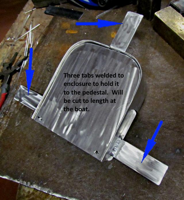
Three tabs of aluminum strap were welded to the enclosure and these, after being cut to length at the boat yard will be used along with the brackets that were made above to hold the enclosure to the tubing at the helm.
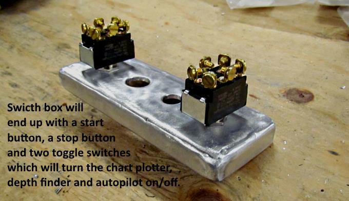
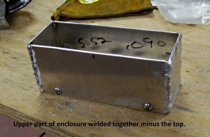
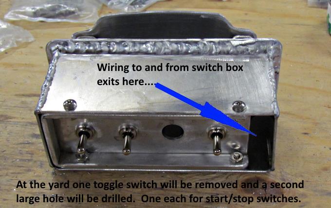
Next up was making a switch box that would control the instruments at the helm and also have a start and stop button switch for the diesel. For some weather protection the switches will be located on the bottom side of the box but will also have weather boots on them.
Here two toggle switches are being used as a trial fit. The holes for the start and stop switches need to be 5/8" in diameter. This is not the final position of the switches as you will see on a later page.
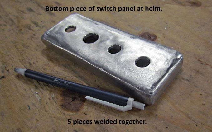
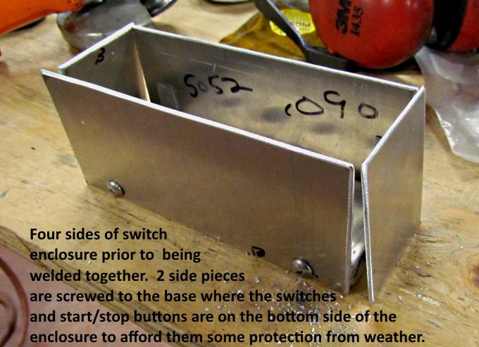
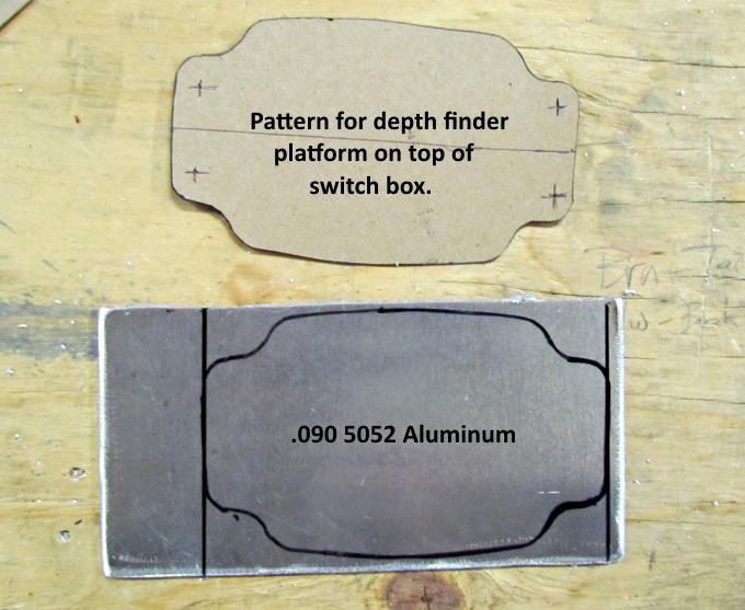
The box was made from separate piece of .090 5052 aluminum. I like it as it welds good and has good corrosion resistant properties.
Upper part of box.
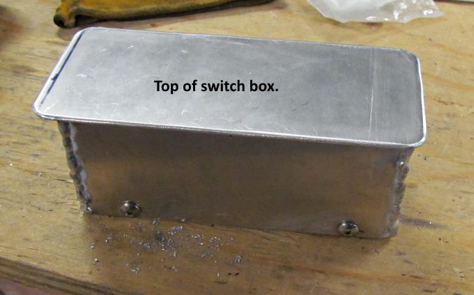
Top piece that will be welded on a little later.
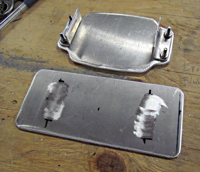
The fish finder/dept finder will mount to the piece above that will sit above the box.
Preparing to ....
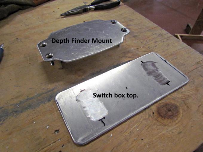
.... weld the brackets for the mount on top of the box where the oxidation has been removed.
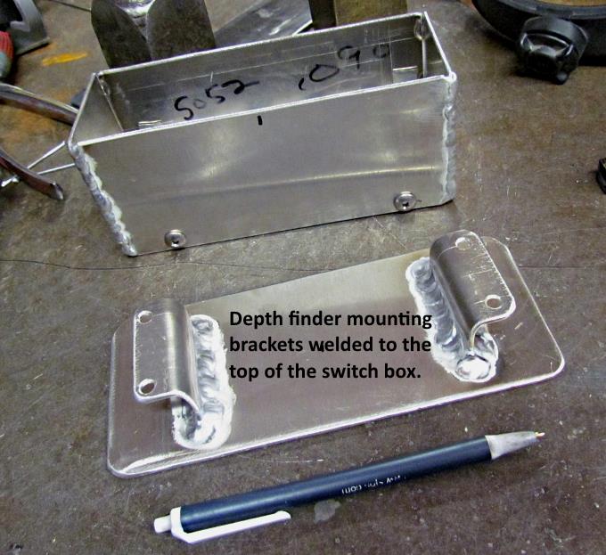
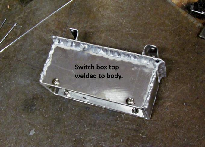
Brackets welded to the top of the box and ...
.... the top welded to the box body.
..
Again the switch configuration was changed around at the boat yard. I made this box work but I sure wish latter that it would of been a little larger as you will see there is a lot of wiring that has to fit inside of it.
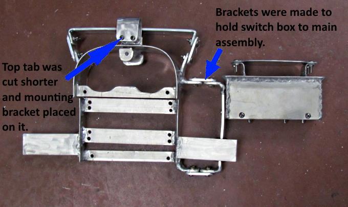
Brackets were made and other pieces of strap cut so that the chartplotter mount could be added to the top of the enclosure.
The top tab was shortened and a bracket attached to it. The bracket will be attached to the top of the pedestal's SS tubing. The side ones were left long to be cut after arriving at the boatyard in Florida.
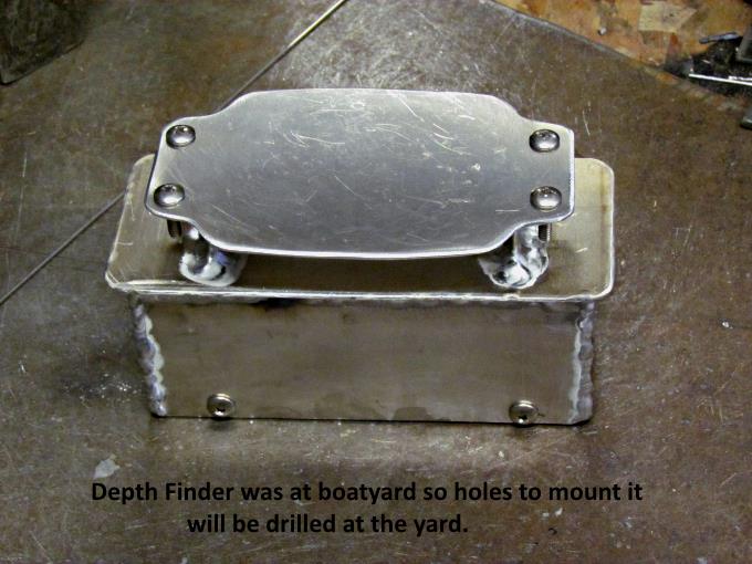
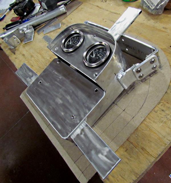
The finished assembly ready to go to the boatyard. The fish finder/depth finder was with the boat at the yard.
==================================================================
............................................................ Next Page If There Is One