.......................................Endeavour Index Page..............Electrical Mods Index Page
....................................................Previous
Page.............................
Next
Page If There Is One
==================================================================
..................................................--- Helm Navigation Station ---
...................................................................................--- Part I ---
==================================================================
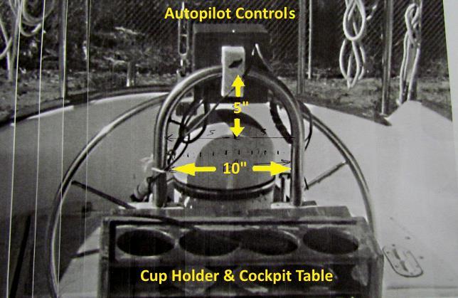
The Endeavour came with a Raymarine ST4000 autopilot at the helm and that was it as far as navigation gear. Actually not totally true as there was an older GPS/chartplotter in a box that I got rid of. We bought a Standard Horizon CPN700i chartplotter and a fish finder/depth and wanted to mount those at the helm along with some switches to control them along with the autopilot. In addition we wanted to be able to start or stop the Perkins 4-108 diesel from the helm also and have an oil pressure and temperature gauge at the helm. A panel was in order to do the above along with being able to send NMEA data between the chartplotter and the Standard Horizon 2100 AIS radio below and the computer below running OpenCPN.
I didn't have the dimensions of the pedestal to make something but our good friend Scott who has a boat at the yard and lives in Florida took the time to get the dimensions I needed to design something.
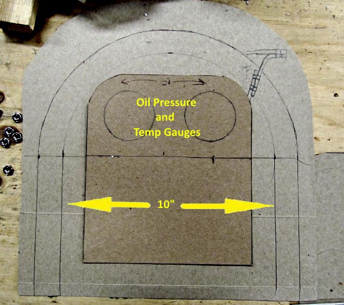
I made a full size drawing of the SS tubing at the pedestal as best I could figure it was from Scott's data and looking at a couple pictures I had taken. I then designed, roughly, what I thought would work as a panel to fit the area.
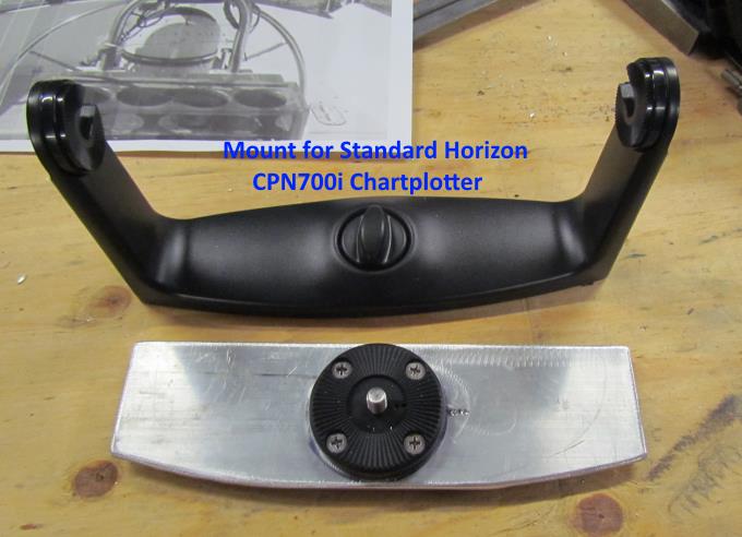
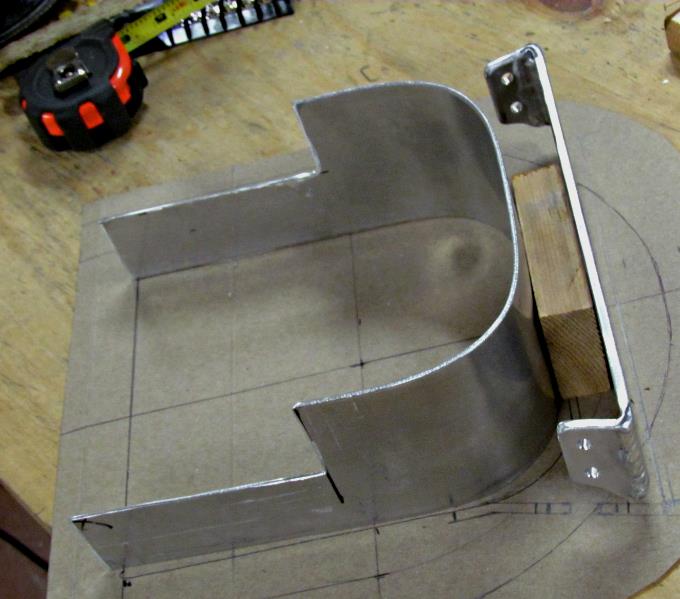
One of the first pieces made from aluminum was a support for the chartplotter's support bracket.
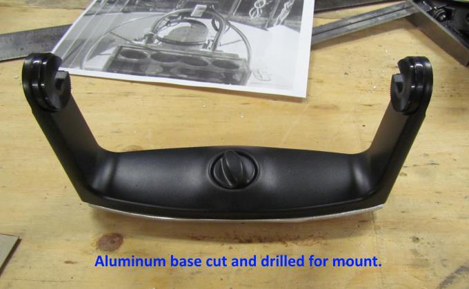
Above the bracket is mounted on the piece of aluminum after it had been cut and drilled.
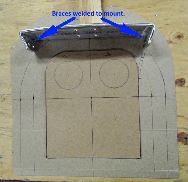
Tabs were welded to the piece that would allow it to be attached to the panel that would be made next.
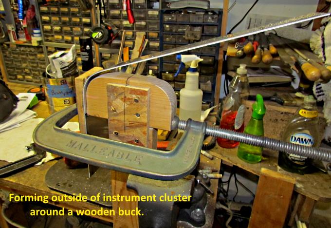
A piece of aluminum strap was used to make the outer shell of the new panel. The strap was bent in steps around a wood buck that was made from the cardboard pattern shown further above (cereal boxes are great for making patterns).
A test fitting for the first two pieces was being done in the picture above.
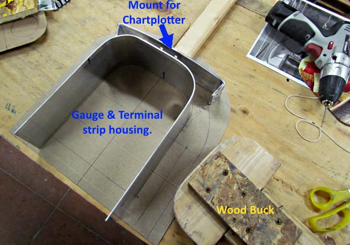
Part of the strap was cut away as the panel won't be the same thickness over its entirety.
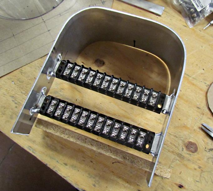
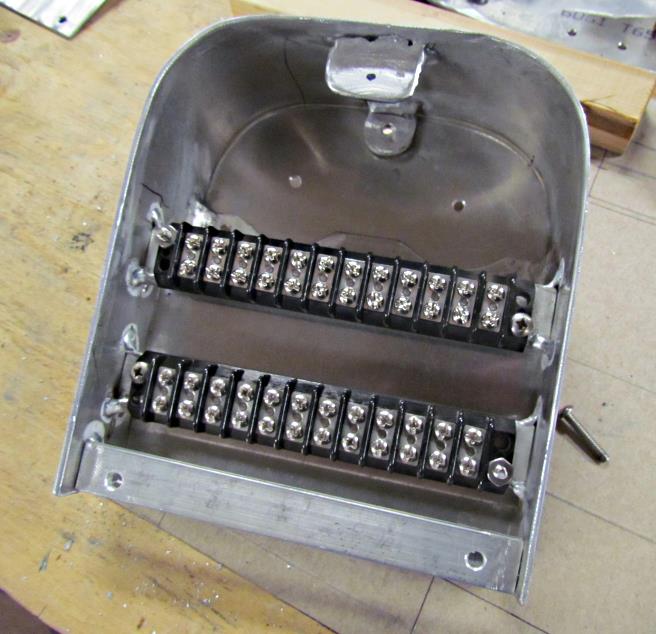
Two pieces of strap were welded in and ...
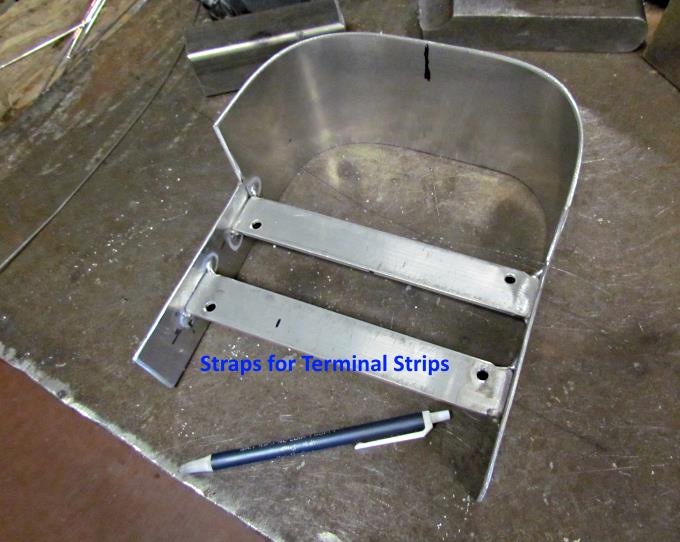
.... terminal strips were test fitted. The terminal strips will help in connecting the various items to a switch box and to allow serial cables to be used to send NMWA data to and from the Nav. station at the helm and the one in the cabin.
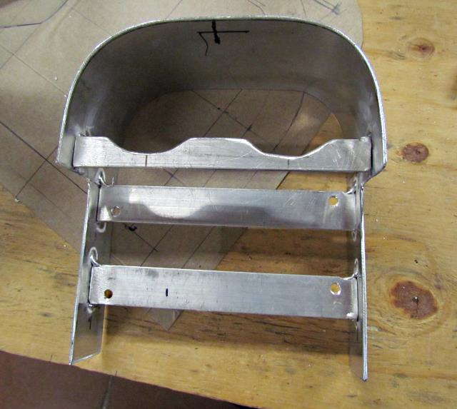
Another piece of strap was added and .....
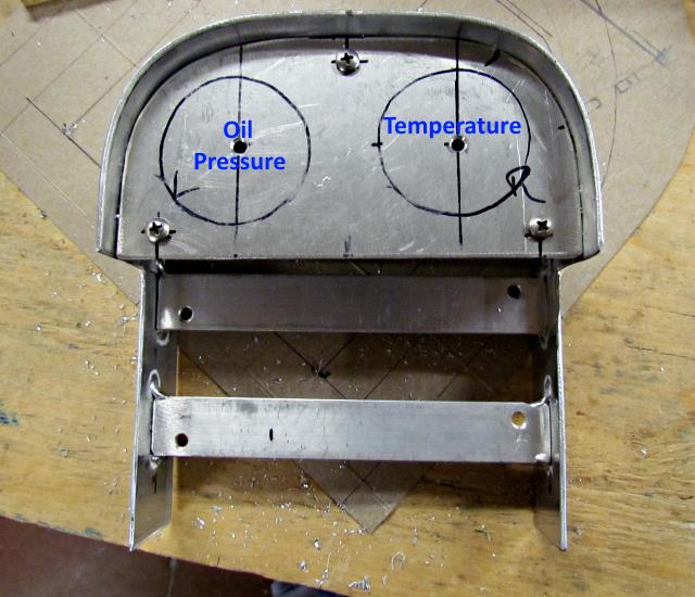
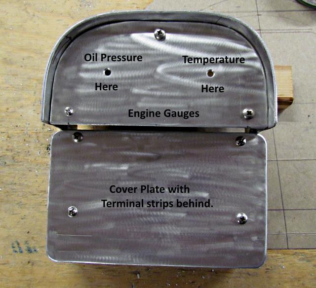
.... a face was made to fit the area for the two gauges.
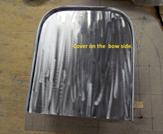
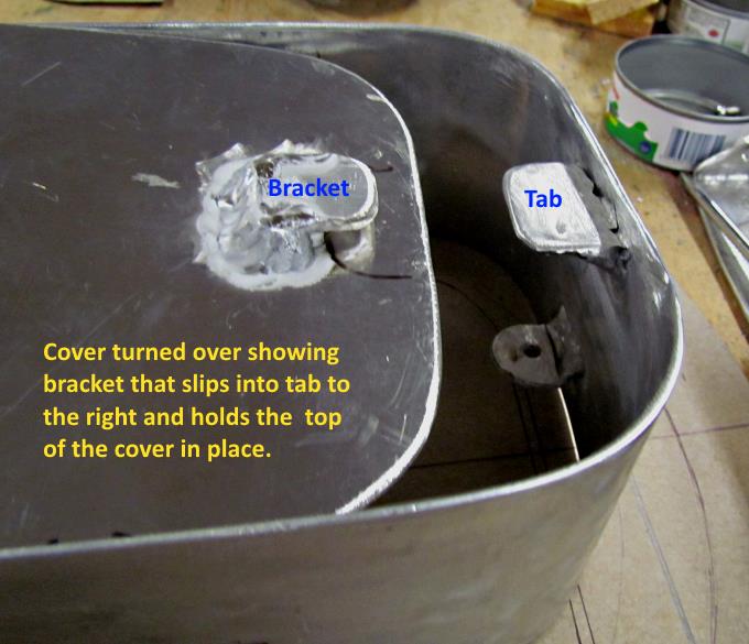
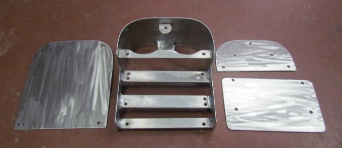
A piece was also fabricated to cover the forward side of the panel.
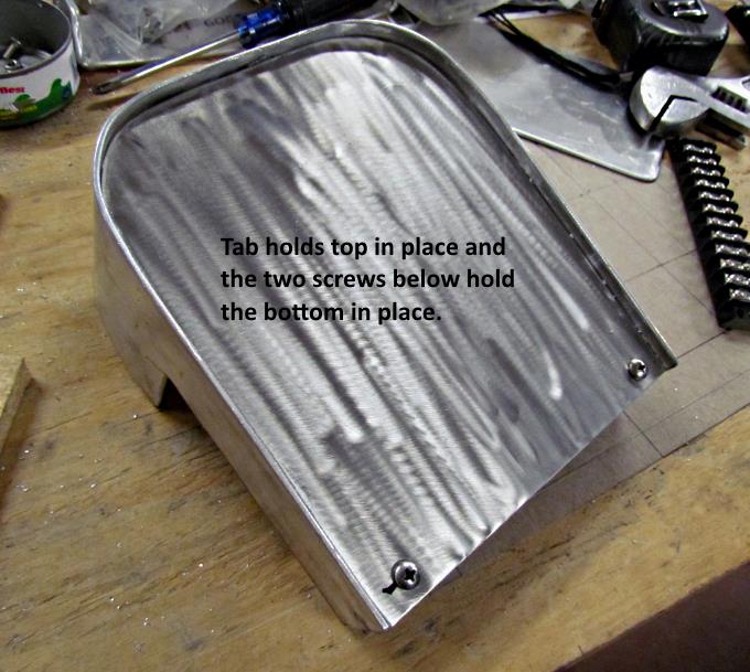
The top of it is held on by a tab inside the panel and with a bracket on the back side of the face. The face is slid up into the tab.
Two screws at the bottom of the face hold it in place.
Another face/cover plate was made and attached to the panel below the gauge face.
The terminal strips face the side that is away from the gauges.
The various pieces to this point.
==================================================================
............................................................ Next Page If There Is One