.......................................Endeavour Index Page..............Electrical Mods Index Page
....................................................Previous
Page.............................
Next
Page If There Is One
==================================================================
.......................--- Final Solar Panel/Controller Wiring --
==================================================================
Prior to 2017 I had only one solar panel mounted on the boat and it was keeping the battery up in case the bilge pump had to run to remove nuisance rain water in the bilge. I'd decided not to mount the other ones just in case there was a hurricane or other disaster that would of damaged panels. One problem about making a mount for panels is that they can change dimensions in the future for the same wattage panel. We do have one additional panel just like the ones below just in case we loose one at some point.
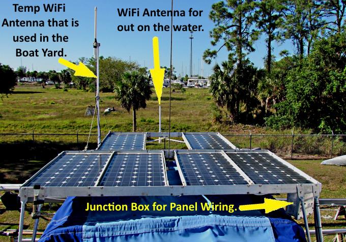
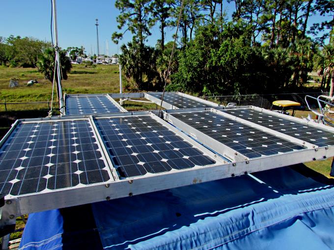
As you can see above all of the panels are now in place, six 80 watt panels for 480 watts of solar in total.
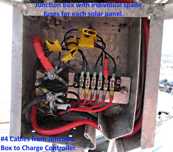
In previous years I'd made the mount for the panels at home, along with the junction box, were the individual panels connect to the cables going down to the solar charge controller.
The wiring from each panel is routed to the junction box and all wiring is oversized for the panel's output to avoid voltage drop between the panels to the charge controller and on to the batteries.
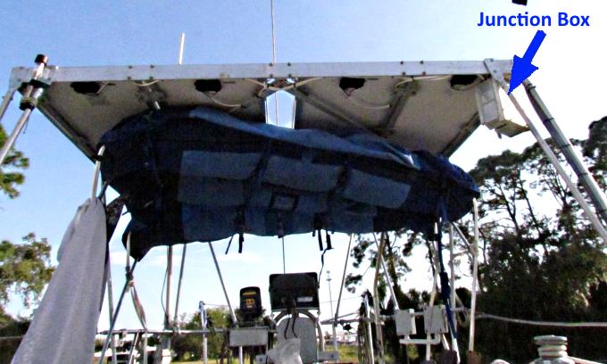
Above I had pulled the bimini back to wire the forward 4 panels to the junction box.
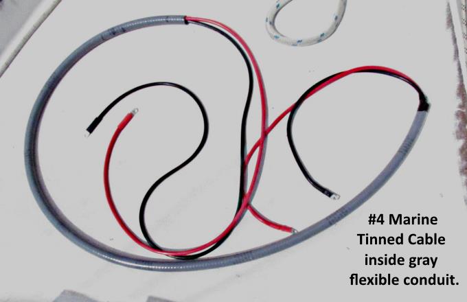
I bought some #4 cables from genuinedealz.com and crimped lugs onto the ends, along with heat shrink, after first running the cable through some gray flexible conduit that I bought at Home Depot.
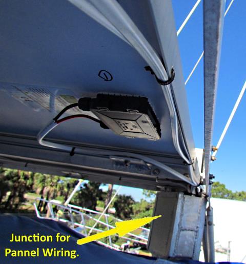
In the junction box there are 6 spade fuses that protect each panel and the wiring to it as there is the potential of 30 amps total from all the panels that could go to a short if one occured in a panel or the wire to the panel. The large cables that enter the box from above and go down the right side above and onto the positive and negative lugs go from the box down to the Blue Sky 3024i charge controller.
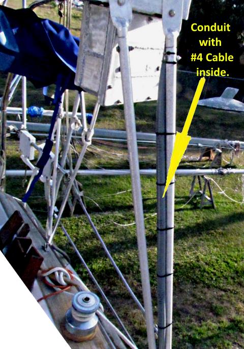
The conduit exits the top of the junction box and travels down one of the support legs for the panel mount.
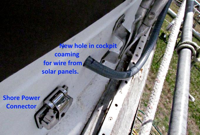
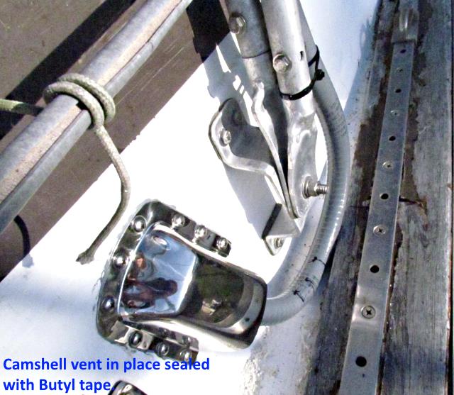
A hole was drilled in the side of the cockpit coaming for the conduit to pass through.
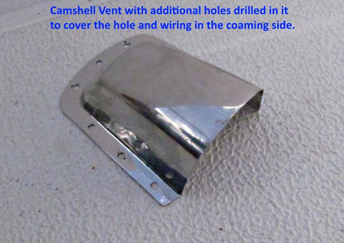
A cam-shell vent was purchased and extra mounting holes were drilled in it and .....
.... it was placed over the conduit where it enters the side of the boat. It was sealed with Butyl tape from Compass Marine.
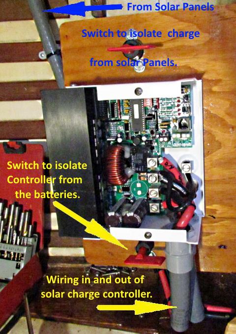
The solar charge controller is almost directly under the coaming where the conduit enters the boat and the batteries are only a few feet the other direction from the controller. Total distance from the panels to the controller and on to the batteries is kept at a minimum to avoid losses in the output of the panels. The wiring is also oversized to keep any voltage losses well under 2% for the entire run. You can also see there is a switch above and below the charge controller so that the run to the panels and the run to the batteries from the controller can be cutoff at any time if so needed. This was recommended to me once by a technician at Blue Seas, the source of the controller. He said it isn't absolutely needed but good practice.
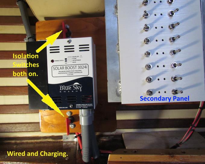
Everything installed and producing power to the boat's batteries. As you can see the Blue Sky Solar Boost 3024i is located next to the Nav. Station and the two switching/distribution panels that are there. From past experience with the MacGregor the 480 watts of solar should provide all the power the boat needs unless there are some very unusual situations. I will be installing a marine 120 volt charger that could be used if there is shore power and will take a Honda 2000 generator on voyages just in case the solar needs to be supplemented or had a problem and of course there is still the alternator on the diesel.
==================================================================
............................................................ Next Page If There Is One