.......................................Endeavour Index Page..............Electrical Mods Index Page
....................................................Previous
Page.............................
Next
Page If There Is One
==================================================================
........--- New Main and Secondary Switch Panels --
................................................................................-- Part 2 ---
==================================================================
The panels were mounted at the boatyard in Florida in the spring of 2017. We arrived there in early December and started work on other projects before getting to mounting the new electrical panels.
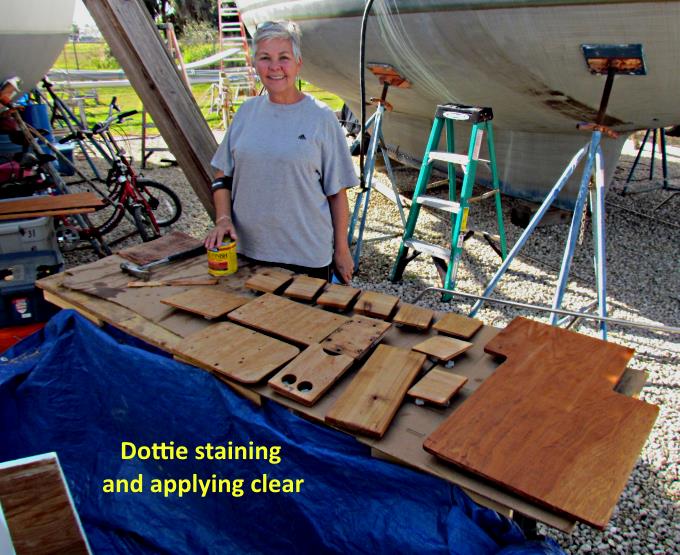
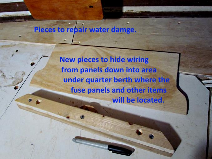
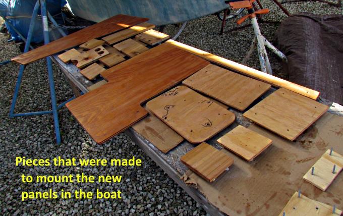
The first order of business was making pieces to mount them and some of the other items on the boat. Some of the pieces above were for the new head and the rest for the new electrical panels.
Dottie was always ready and willing to work on these projects.
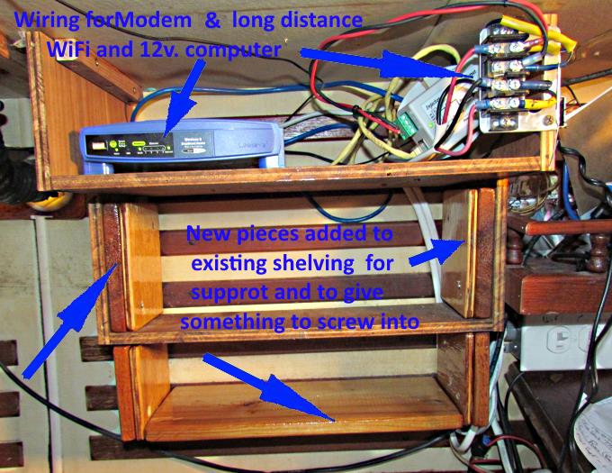
The prior owner had put in some shelving next to the Nav. Station and they were modified some and added to and served as a foundation in mounting the new panels.
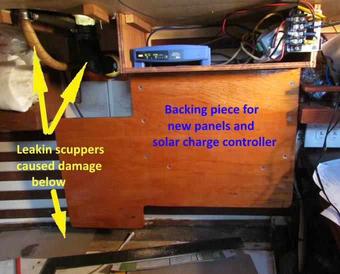
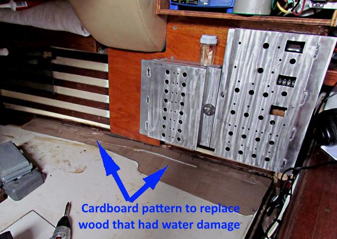
A larger piece of plywood was used as the main mounting board and it was screwed to the old modified shelving. While doing this we found that there was water damage to a plywood piece that was at the edge of the quarter berth. I replaced the leaking scupper hoses shown with new better ones and below you will see that a new piece was made to replace the damaged one.
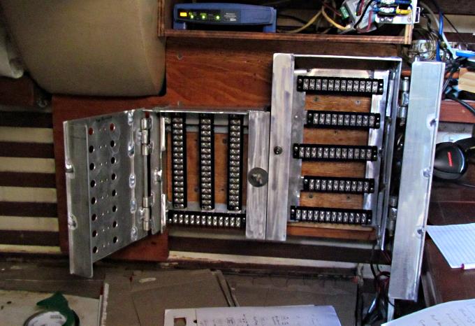
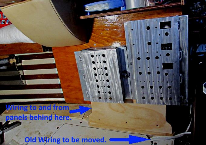
Then the new panels were screwed to it. This was easily done by locating the panels and screwing through their plywood backs into the new mounting board.
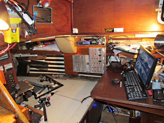
This picture shows the edge of the companionway, lower left, and the boat's Nav. Station, that is just ahead of the quarter berth. The switch panels will be very easy to access in this new location.
Ready for toggle switches and wiring.
A card board pattern was make for the replacement wood.
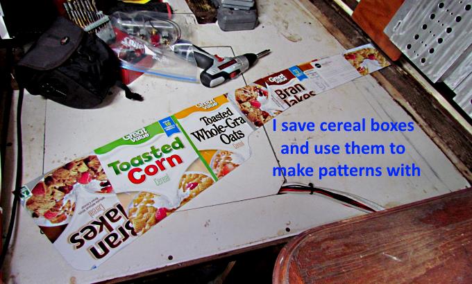
Good thing I like cereal as the boxes are perfect for making patterns with. I use them at home also for numerous projects.
I wasn't happy with the original pattern so made a new one that would work better with how I wanted to run the wiring from the panels to underneath the quarter berth.
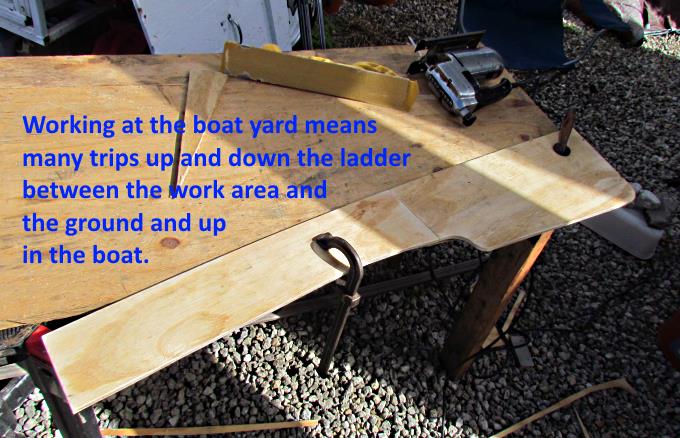
Sometimes it is frustrating in how long it takes to finish projects compared to working in the shop at home. You are working in the same area you are leaving in so you constantly have to move things in the boat. A lot of your work is down on the ground under the boat and requires you to put things away every day there and also means lots of trips up and down the ladder while working on a project. If you are looking at buying a new boat consider that it will take much longer than you anticipated to finish projects on it. At this point I had spent at least 10 months working on the boat from the time it was purchased and it still wasn't back in the water. This was about 6 years after the purchase as other 'dealing with life things' had also happened.
.
.
I was also changing all of the primary wiring out on the boat and installing fuse blocks and main switches below the quarter berth area for easy access. To make it easy access I cutout a new removable panel in the quarter berth. I show making the new access on another page. Holes were cut into the one area so that wiring could be passed through going to and from the panels. It is hidden by a piece in the prior picture.
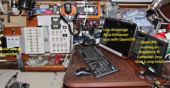
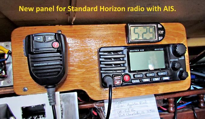
The new panels are conveniently located next to where you sit at the Nav Station. The Standard Horizon VHF radio with AIS (top center) is now in a good location also. Located on the Nav. Station is the main computer, a Asus 2 in 1 computer that I love. I have OpenCPN on it as a backup to the Raspberry Pi and the chartplotter at the helm. The Asus has a very low amp draw compared to my last laptop.
To the right of it is the 10” screen for the Raspberry Pi computer that is running OpenCPN. The Pi and monitor use less than 1 amp and I have an AIS daughter board in the Pi that is connected to a separate antenna and shows AIS targets on OpenCPN. The Standard Horizon radio also receives AIS targets and sends that info to the chartplotter at the helm. The Raspberry Pi sells for $35 and the monitor was $100 and the AIS daughter board, antenna and wiring ran another $130 or so. So for less than $300 total you can have another chartplotter with a 10” or larger monitor running OpenCPN with AIS that draws less than 1 amp.
The Blue Sky MPPT solar charge controller is mounted just to the left of the electrical panels.
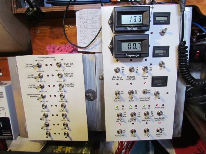
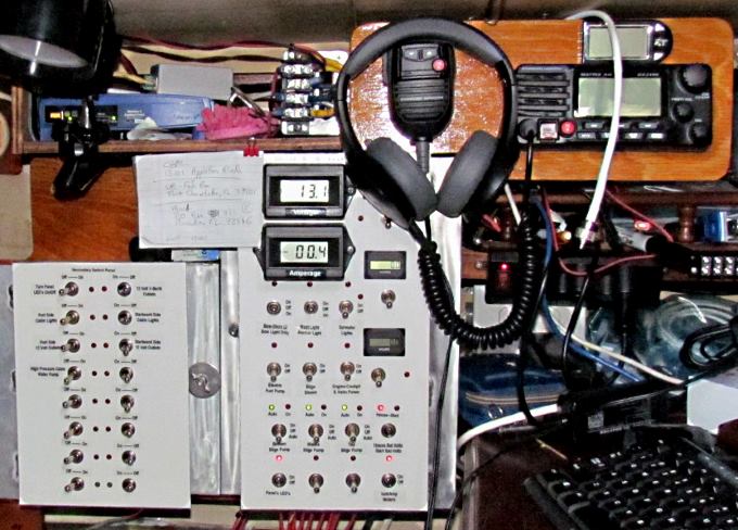
When the picture above was taken the secondary panel to the left was labeled but not wired to the circuits shown on it. They were still controlled by the original panel at the companionway. A number of the circuits on the main panel to the right have been wired but some of them were also still on the boat's original panel.
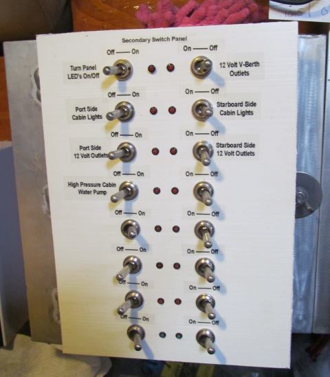
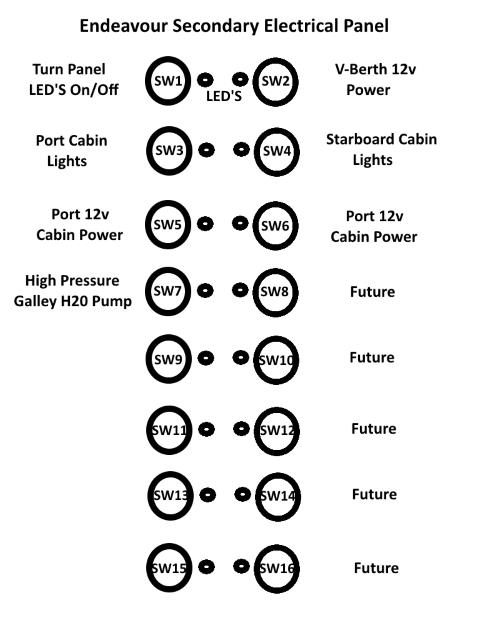
Above is a close up of the secondary switch panel. There will be a number of switches unused at this point but they are there for future expansion if needed along with a couple on the main switch panel.
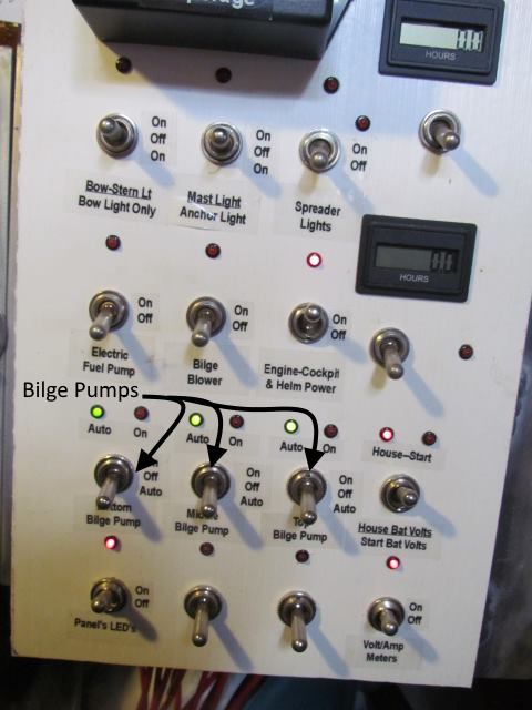
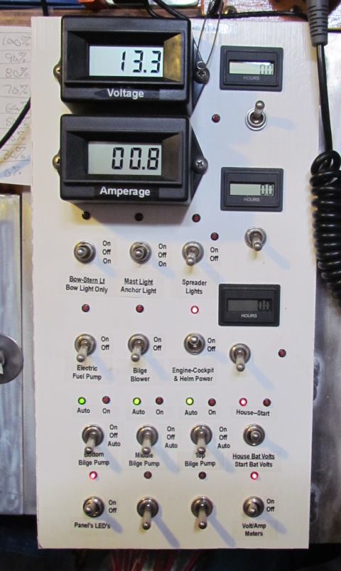
I had installed 3 new bilge pumps to replace the old one that didn't work and wired those to the new Main Panel at this time. I also wired up the volt and amp meters. You can throw a switch and read the voltage on either the house bank of batteries or the start battery. Another switch turns off the meters and another one is used to turn off all the LED's if needed. When we return to the boat more wiring from the old panel will be moved to this one along with additional new circuits.
In the picture above you can see the hour meters installed. They can be connected to any circuit I'd like to monitor.
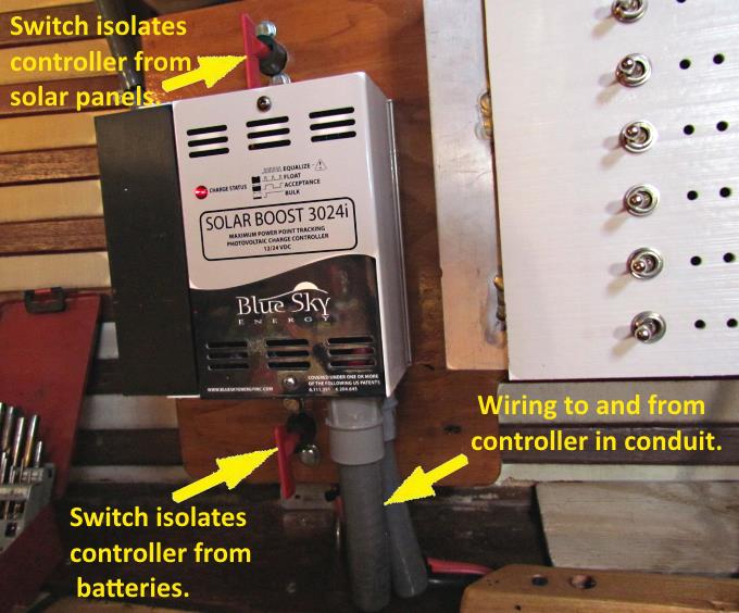
At this time I also added all the solar panels to the solar panel mount above the cockpit. Up until now I only had one panel mounted and it maintained a battery for the bilge pump that is used to remove any rain water that might find its way into the bilge when we aren't there. The boat actually stays quite dry. The Blue Sky MPPT controller was moved to its new home and wired to the panels and batteries. When I installed a Blue Sky MPPT on the MacGregor I talked to one of their tech guys and he said that it was best if you could isolate it from the batteries and panel if you had to service it for any reason so I added switches above and below it to accomplish that.
At this time a panel was also made to mount the radio in the Nav. Station area. We will get a RAM mike for this radio probably to use in the cockpit but I also use a handheld there while underway. The radio will be connected to the Standard Horizon CPN700i chartplotter at the helm and to the computer below running OpenCPN so that AIS targets are shown on both.
We believe that this new location for the switch panels along with the new primary wiring will be a big improvement over what was in the boat.
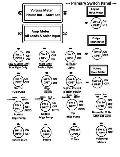
Above is the switch layout on the Primary Panel and their functions. SW1 and SW2 let me choose the correct lights for sailing or running under power or anchored. Sailing is SW1 up. Motoring you put SW1 and SW2 either up or down in unison and the correct lights will be displayed. On anchor SW2 is down. SW10 switches the volt meter between the house bank and the start battery. Sw7-8-9 control the three bilge pumps, either off, manual on, or auto on controlled by the float switch. The bottom bilge is smaller and a nuisance pump.
Above is the Secondary Electrical switch layout with room for growth in the future.
==================================================================
............................................................ Next Page If There Is One