.......................................Endeavour Index Page..............Electrical Mods Index Page
....................................................Previous
Page.............................
Next
Page If There Is One
==================================================================
........--- New Main and Secondary Switch Panels --
................................................................................-- Part 1 ---
==================================================================
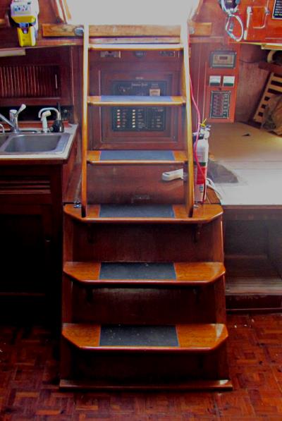
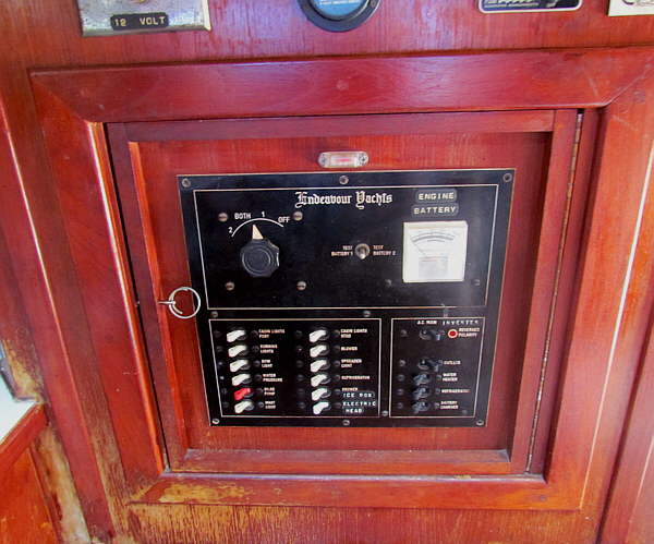
Below is the original electrical distribution panel. It and the rest of the boats wiring was probably up to date when the boat was built but out of date to today's standards. It was decided to leave this panel for old times sake but to move all of the circuits from it and newer circuits to a new Main Panel and a Secondary Panel. Also all of the boat's primary wiring will be brought up to current standards at the same time.
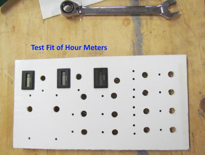
I decided to make the electrical panels after I couldn't really find any that meet my requirements as most are pretty general in use. Using these panels I can pick and choose different toggle switches (double and single pole and double or single throw). This will allow the use of switches with a lot of functionality. For instance each of the 3 bilge pump switches will be center off, up for manual on and down for auto mode where the bilge pump will be turned on and off with the float switch with LED's showing which mode the switch is in. The panels will also incorporate Volt and Amp meters and hour meters all on the same panel.
Besides being antiquated the old panel .....
... was located behind the companionway and ....
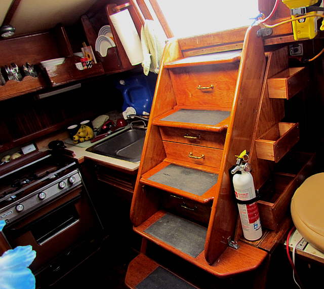
.... we had added storage under the companionway in the way of drawers that made the galley much more user friendly by greatly increasing storage there that was easy to get to. More about it ( HERE ).
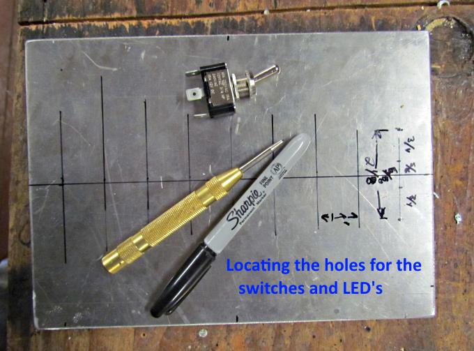
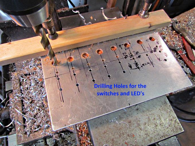
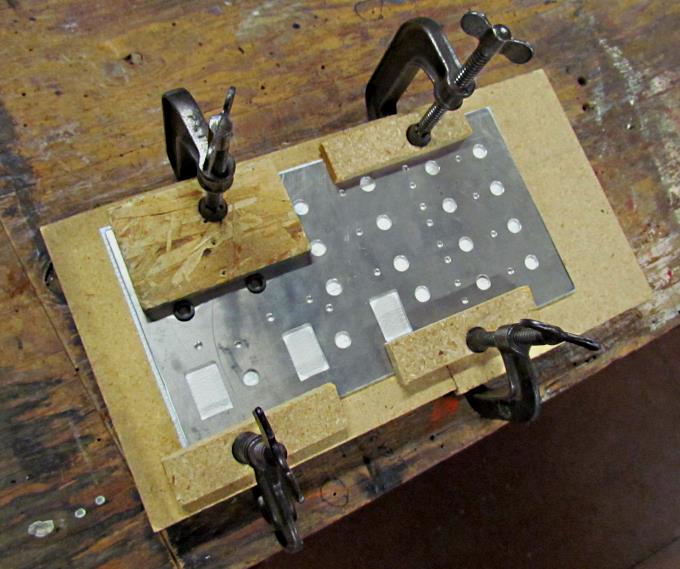
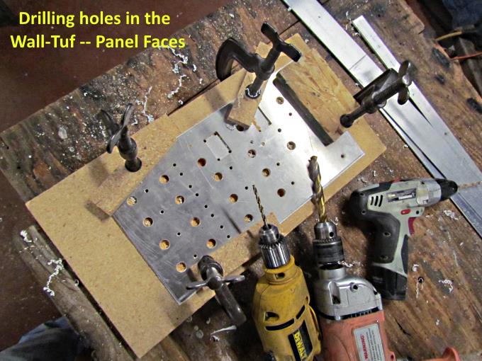
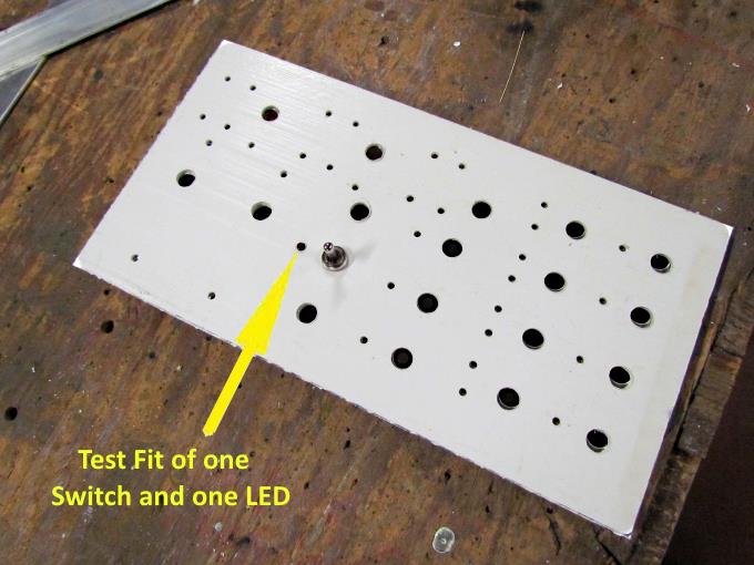
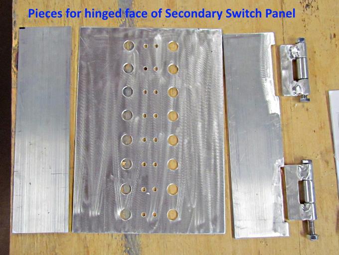
On this page you will see the Main and Secondary Electrical Panel boxes being made. I won't always show pictures of both under construction and most are self-explanatory. Above I'm laying out where to drill the holes for the toggle switches and the LED's that will show if the circuit is active or not.
.
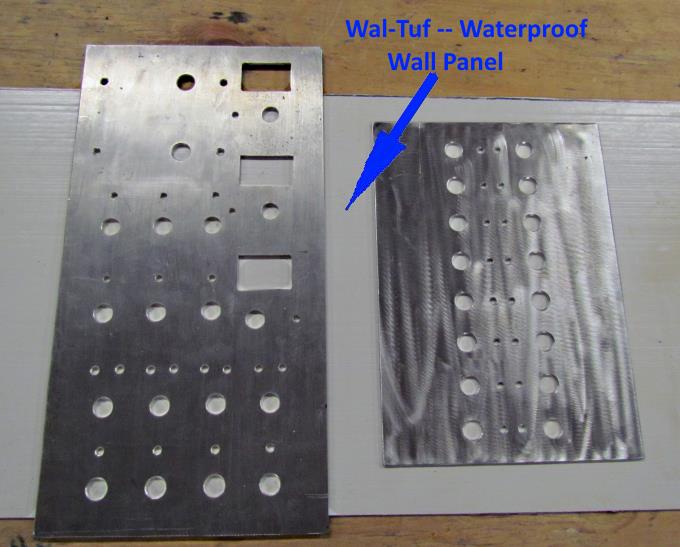
I had some wall board, like what is used in bathrooms and such that is smooth on one side and has a pebble texture on the other. I wanted to use the smooth side and decided on these as I'll print labels with our P-Touch label machine that will show the function of each switch.
.
.
.
.
.
.
.
.
.
.
.
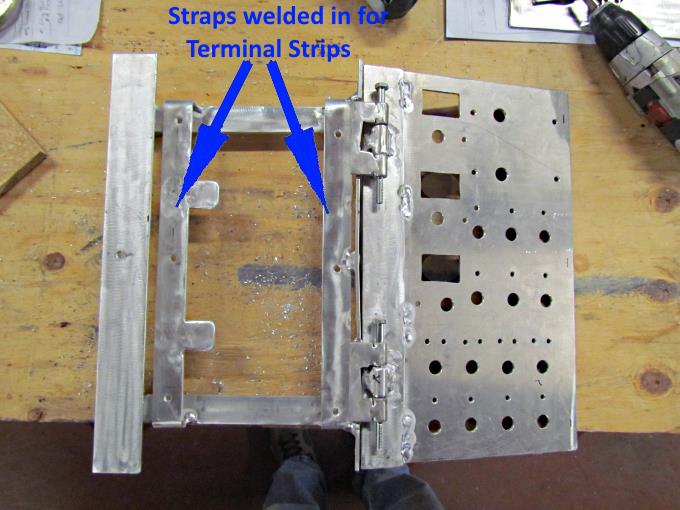
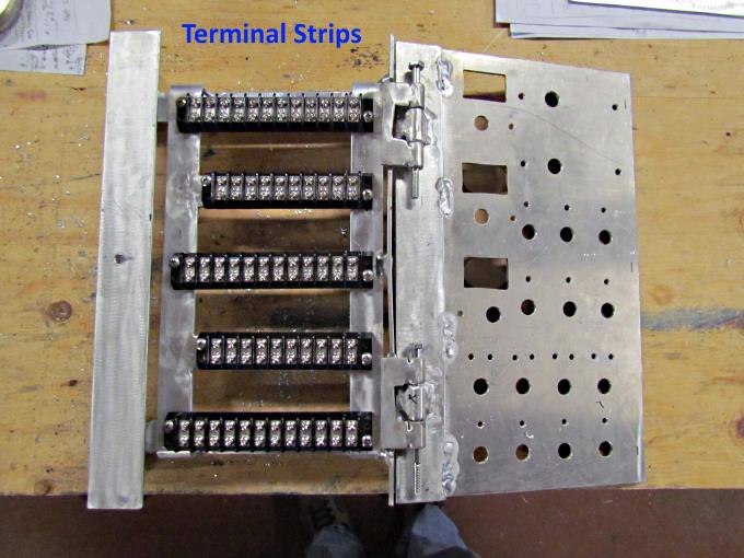
Wiring will go from the fuse blocks to the terminal strips and from there to the switches on that circuit if there are more than one. The switched current will then go from the switch back to the terminal strip and from there to the device/devices the switch is controlling the current to. This adds another connection or two between the current's source and it's destination but I like the flexibility of working on individual circuits that it offers vs. wiring directly to the switch.
.
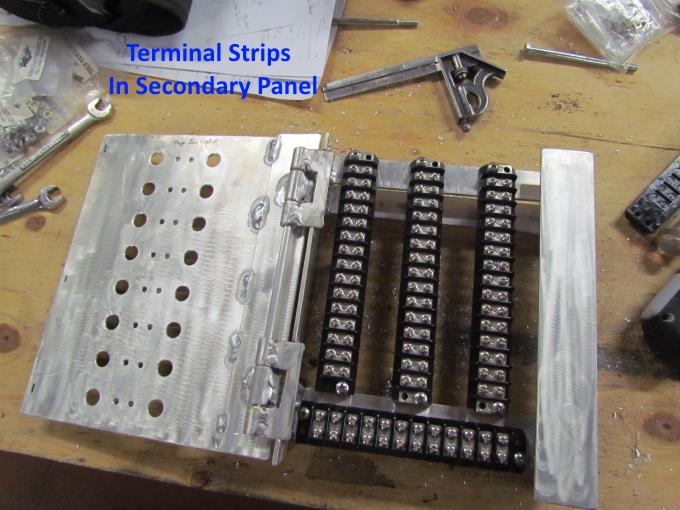
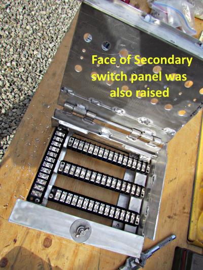
Terminal strips mounted in the Secondary switch panel. Later you will see the circuits that both panels control.
.
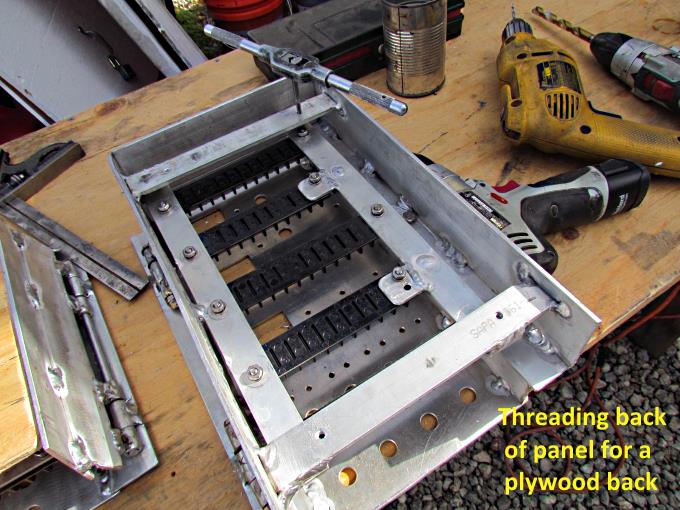
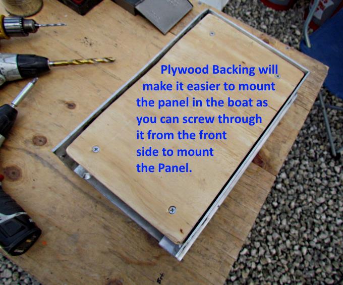
The plywood panel backing will make it much easier to mount the panels in the boat as I can screw through them from the front side at any place that is convenient for me.
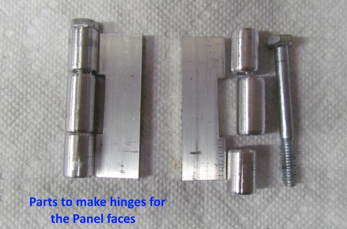
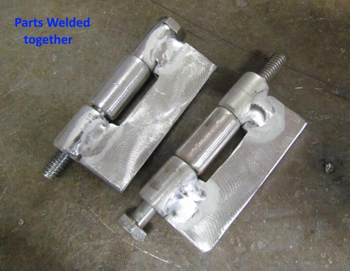
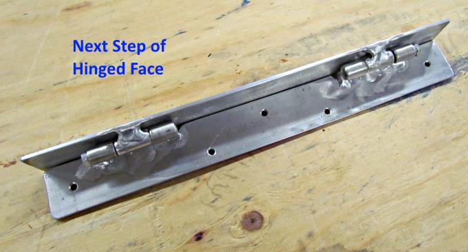
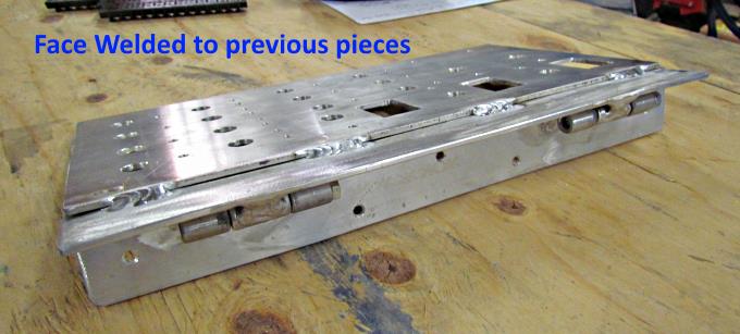
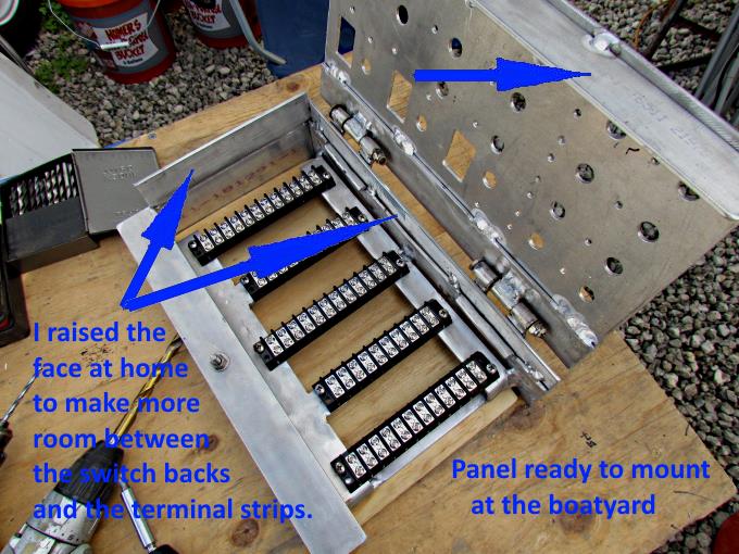
I wanted to wire the panels to some degree at home but ran out of time but did mount a couple switches in them and then came to realize that the face was too close to the terminal strips. It would be hard to fit the wiring in from the switch backs to the terminal strips. I cut the hinges off their original locations and welded them to risers that moved the faces further above the panel body.
The next page will show mounting the panels in the boat and adding switches and gauges to them.
==================================================================
............................................................ Next Page If There Is One