.......................................Endeavour Index Page..............Electrical Mods Index Page
....................................................Previous
Page.............................
Next
Page If There Is One
==================================================================
.......--- Helm Navigation Station/Running Wiring to Helm --
...............................................................................--- Part V ---
==================================================================
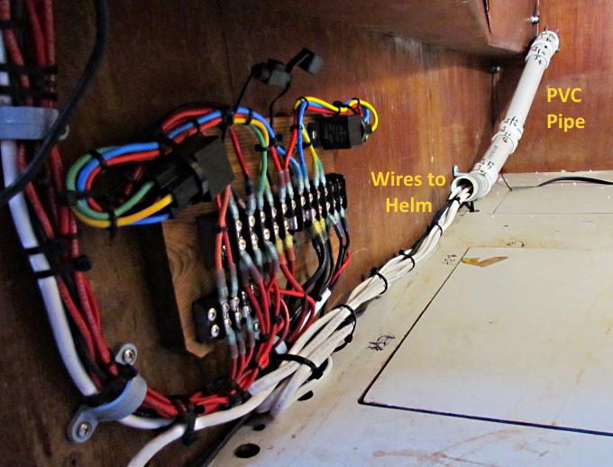
On this page the wiring is run to the helm from mainly the terminal strip on the engine side of the quarter berth. In addition a long extension wire is run from the fish finder/depth finder past the quarter berth all the way forward under the V-berth where the transducer will be placed. Also a multi-wire cable is run from the helm to the interior Nav. Station area to be used to carry serial NMEA signals to and from the helm and an AIS VHF radio and a computer at the interior Nav. Station. Also the Raymarine ST4000 fluxgate compass and wire were moved into the boat by the companion way so that wire had to be routed through this area also.
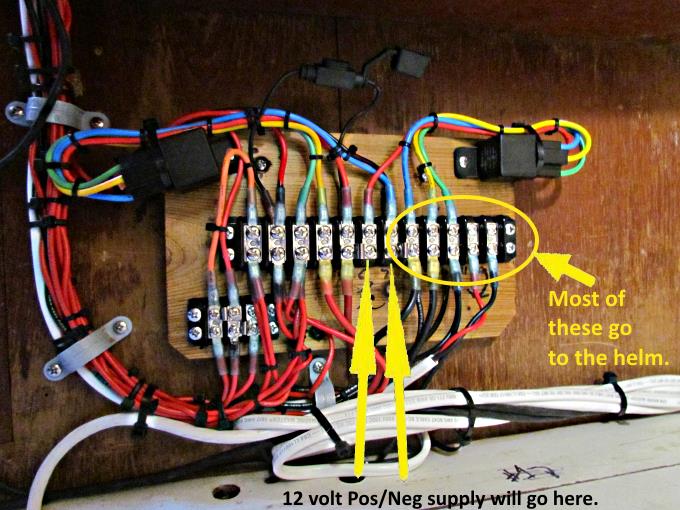
Most of the helm wires go to the right side of the terminal strip but some, such as the wire to the 'start solenoid relay' go to the other end. At this point the 12 supply wires have not been attached so there is no live current at the strip at this point.
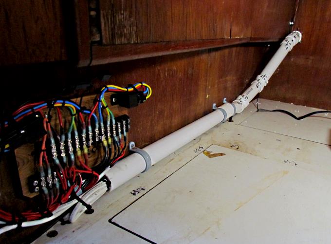
The wiring was run through the PVC pipe fittings shown at the back of the quarter berth. At that point the fittings were not attached to each other. Once all the wires were run they were put together but not glued. Some short screws hold each joint together, just in case more wires need to be run in the future.
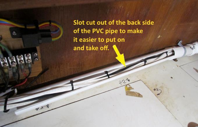
Next a long slot was cut on the backside of a single longer piece of PVC pipe. That way in the future it can be taken off easily also.
The pipe was rotated so that the slot was on the back side and then clamped to the wall.
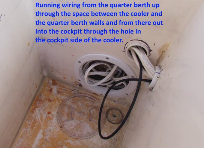
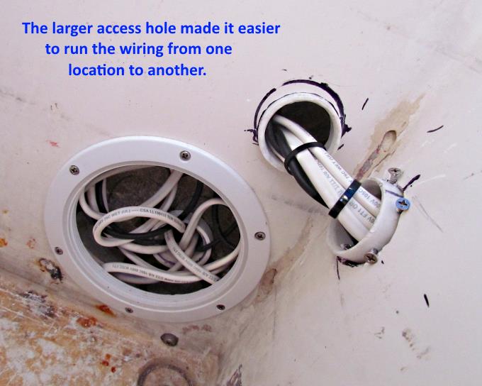
All the wires had been run into the cooler where they were turned and run up into the cavity where the insulation had been. From there through the fitting in the wall above the access port and out of the cooler through the fitting to the right above.
The larger access port made it handy to turn the wire and run it up to the other hole above it. This was mainly done to keep the intrusion of the wires in the cooler to a minimum and to exit them above the floor of the cockpit.
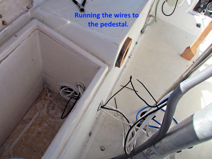
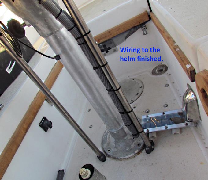
The wires were run one at a time from the quarter berth to up on the pedestal at the helm.
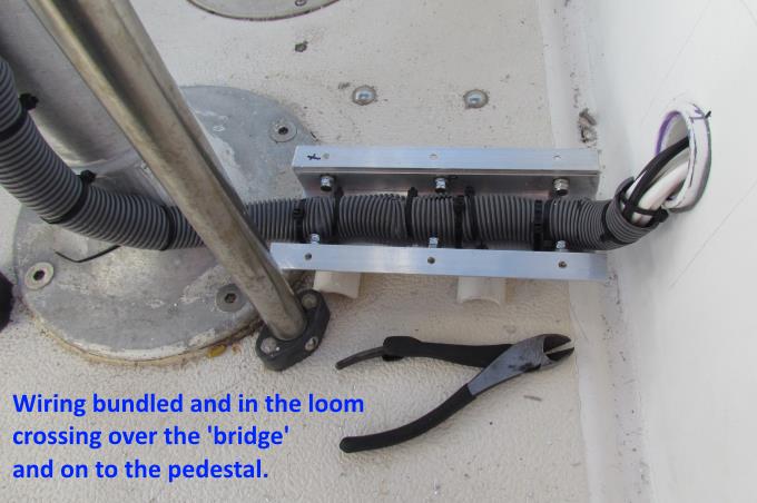
Once all of them were run they were provided some protection by placing them in the gray loom and running them over to the pedestal on the little bridge which keeps them off the cockpit floor.
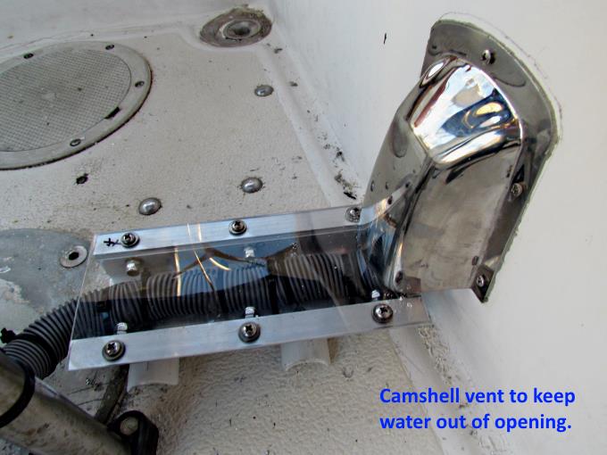
A cam-shell vent was installed to keep water out of the opening going to the cooler's interior and a clear piece of plexiglass was put on the top of the little bridge.
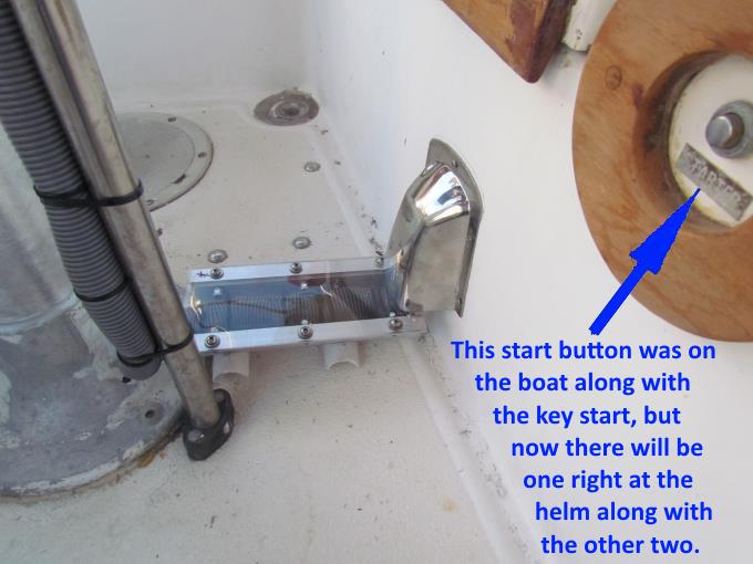
In this picture you can see a start button for the diesel. You could previously start the engine here or forward at the engine panel by the companionway. I wanted a more convenient start button at the help so one was being added at this time. The one above and the key switch are still functional.
The rest of the wiring going up the pedestal was also placed in the loom. This finishes the wiring to and from the helm. Now onto the wiring for the various instruments and switches at the helm.
==================================================================
............................................................ Next Page If There Is One