.......................................Endeavour Index Page..............Electrical Mods Index Page
....................................................Previous
Page.............................
Next
Page If There Is One
==================================================================
.......--- Helm Navigation Station/Wiring Path to Helm --
...............................................................................--- Part IV ---
==================================================================
.
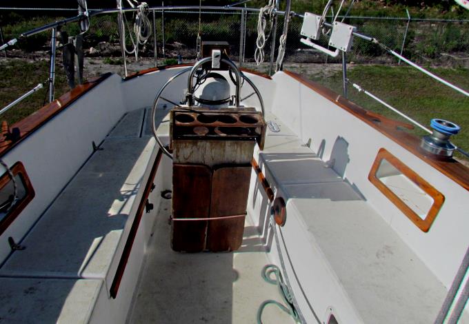
Adding a chartplotter, fish finder/depth finder, engine gauges, engine control switches and NMEA wiring between the helm and the interior navigation center meant getting a lot of wiring to and from the pedestal at the helm. There were two electrical wires running up the SS tubing at the helm for a 12 volt outlet and for the auto-pilot. There was room for more there.
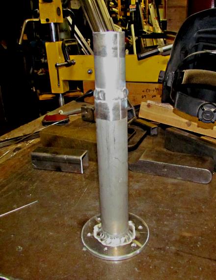
At home I made a vertical piece of tubing that I thought might go between the back side of the cockpit table and the steering pedestal. Arriving at the boat I saw that wasn't going to work due to the limited space there, both in the cockpit and below the cockpit, where there was a cross-member in the way along with the steering gear.
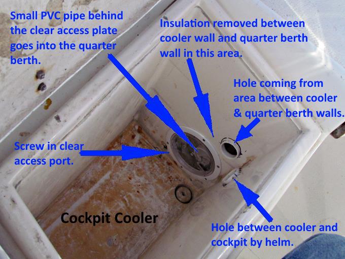
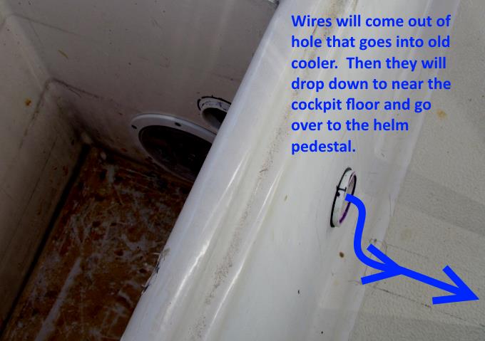
I gave up on coming up from below and also didn't like having to seal that option from the water that gets in the cockpit from rain and possibly sea spray. Just to the port side of the helm is a compartment at is for use as a cooler. It is insulated to a small degree and has a drain hole at the bottom. We use it for storage and would never use it for a cooler. I decided to go from the quarter berth into the cooler and then out of the cooler into the cockpit and then down near the cockpit floor and across to the pedestal and up it to the new helm navigation enclosure. The wiring would be in only a small part of the cooler and could still be used for that if someone in the future so desired.
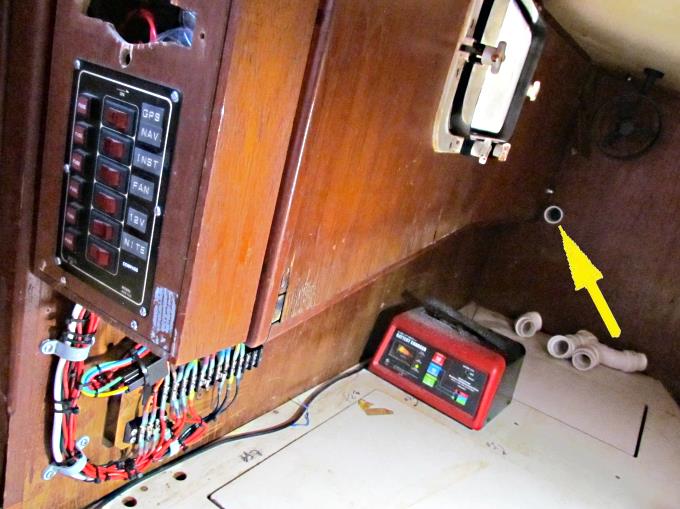
A hole was drilled through the back quarter berth wall and into the cooler, see arrow. It was made just large enough for a piece of PVC pipe to line it for the wiring to run through.
I put in an access plate with a clear face in the cooler where the hole from the quarter berth pierced the cooler. There is insulation between the cooler wall and the quarter berth wall and I removed it around that area. That will allow wiring to come from the quarter berth and turn up before the access plate to the hole shown above it. The wire will come out that hole and make a 90 degree turn and go out the side of the cooler into the cockpit. The access plate is there so that you can turn the wire and run it up where the insulation was.
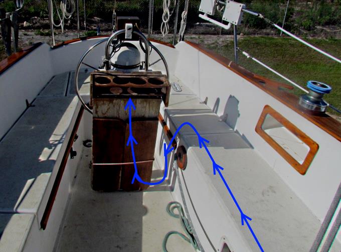
The wire will come out the side of the cooler into the cockpit and drop down near to the floor and cross to the pedestal and then up it.
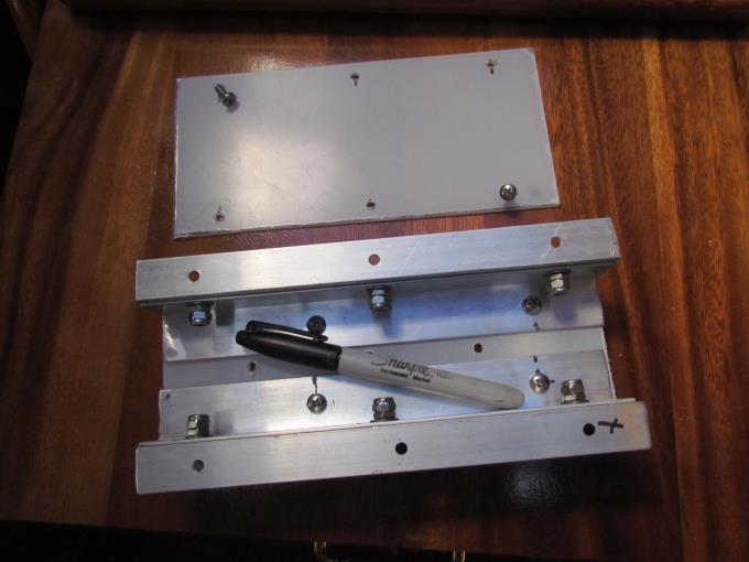
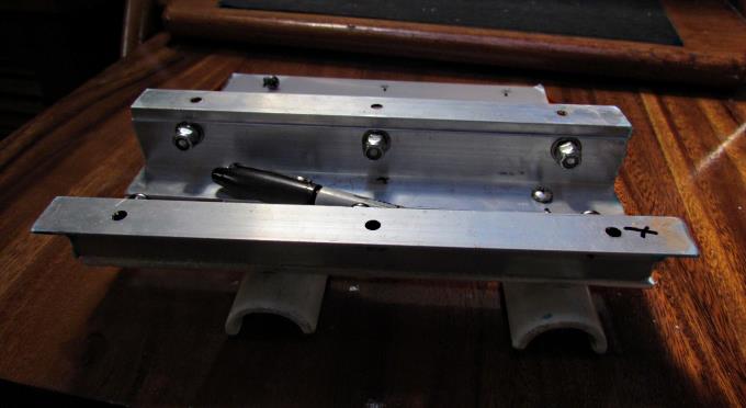
I wanted to put the wiring in conduit and keep it off the cockpit floor where water could be present so made the little bridge enclosure shown above and in the next couple pictures.
It was made for some aluminum angle and some plexiglass from Home Depot along with some PVC pipe cut in half for short feet to raise it off the cockpit floor.
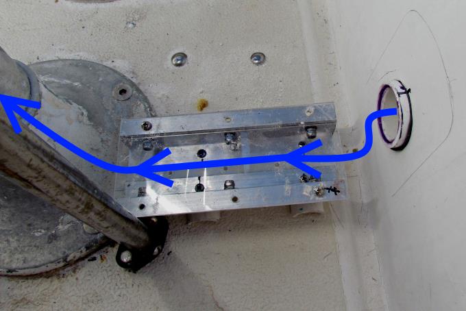
Above it is shown in place and later you will see how it carries the wiring over this short space. With the wheel on at the helm it isn't easy to get past it going forward and you can't hardly step in this area to go past the helm so I don't see it being there as an obstacle as far as getting to and from the helm and you don't sit in that area either.
==================================================================
............................................................ Next Page If There Is One