.................................. Return to Sumner's Home Page....
Return to N Scale RR Main Menu... Return to Test Track Menu
=========================================
..............Previous Page..............................Next Page If There Is One
=========================================
….......--- Test Track to go Under Layout ---
…..............--- Part VI – Laying Track ---
=========================================
I'm not going to go into much detail laying track as this is covered in numerous places on the internet.
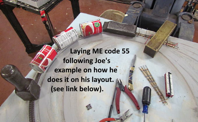
I love how Joe lays track on his Sayrehurst Secondary layout. You can find one of his videos that I used ( HERE ) along with links to others. So most of what I've done laying cork roadbed and track is mimicking what Joe does. Thanks again Joe for putting you methods up there.
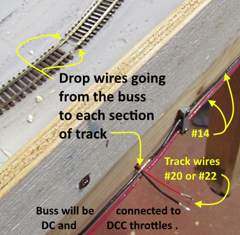
I'm getting in the habit to have a track wiring drop in every section of flex track or about the equivalent run of track. Above I did this under the rail joiners for two shorter sections of track. I'm using either 20 or 22 gauge wire depending on the distance from the rails to the buss at the edge of the layout. You'll see pictures of the buss that circles the layout along the face. It is #14 solid wire and I'll get into why I'm wiring the layout in this manner and how probably on the next page. The driving reason though is at 77 (when I wrote this) I'm not wanting to work under the layout any more than necessary.
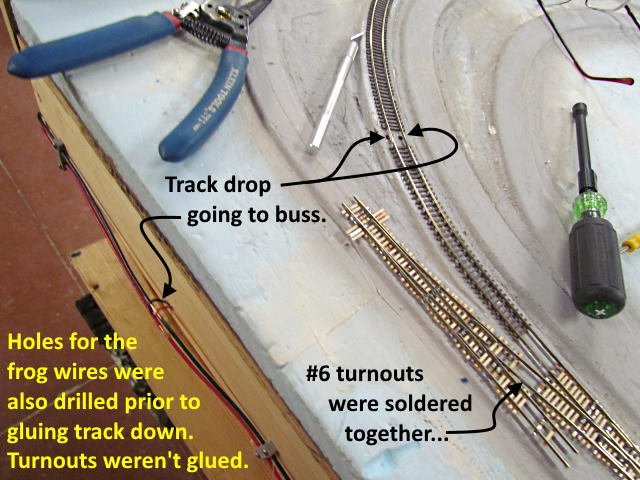
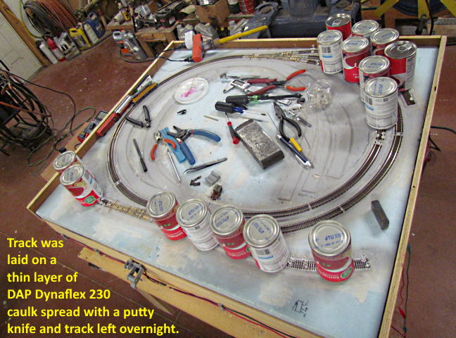
Before gluing the track down I also drill any holes I need for other drops like at the frogs of the turnouts. I soldered the stock rails of the two turnouts above together before proceeding with the other tracks off the left one.
Near the solder joint I also gaped the two turnouts where they meet. This was necessary as the tracks going off the left turnout will be switched to a program track when needed. So they needed to be isolated from the main with the gaps.
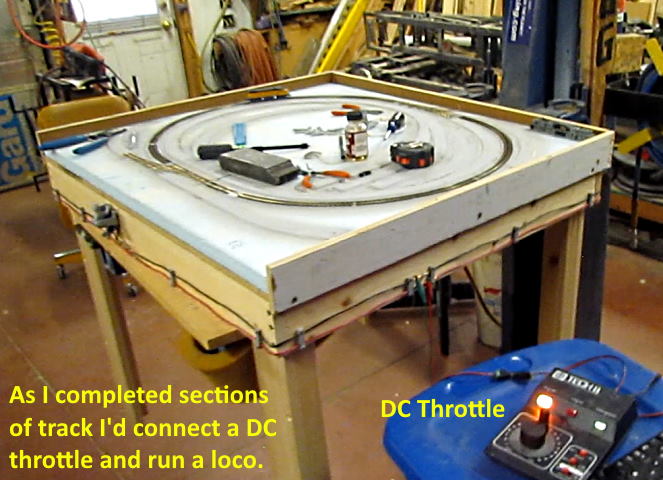
After laying a section of track I test it with a loco. Actually I normally do the testing with a 4 axle, a 6 axle and a GE U50 the has four 4 axle sets and a short FM H-12-44 switcher. When I can run all of those over the track and through the turnouts I fell pretty good about the track.
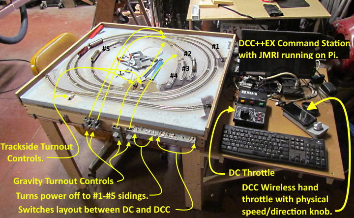
Above I'm using a DC throttle but I'm also able to connect my DCC++EX Command Station to the track to run DCC locos. More about that and the wiring in general coming on the following pages.
The video above or ( HERE ) is a short video of testing the new track section.
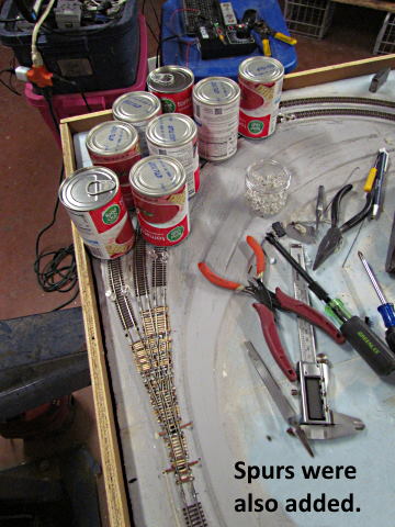
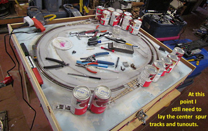
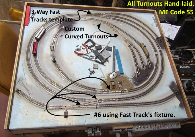
With the main in place and the turnouts on it in place I proceeded to start laying the spur tracks. The main purpose of the test track will be to have a simple oval to break in or test locos and a place to program them. The inclusion of the turnouts and spurs was to gain experience in laying them and to also let me test my hand-laid turnouts and the different options I've come up with to control them.
.
.
.
At this point I don't think I can squeeze any more track onto the small layout and it has served its purpose. I feel comfortable laying track and turnouts, installing turnout controls and any wiring that I'll have to do with the exception of reversing loops and will use Tam Valley auto-reversers for those so that should be easy.
I'll keep this layout and use it to test DC locos that I have prior to decoder installs. After the install I'll program the decoders on this layout probably and I can also run DC or DCC locos in on this layout.
Above is an overview of the wiring and in a few more pages the track wiring will be discussed in more detail.
=========================================
...........................On..............e.........Next Page If There Is One