.................................. Return to Sumner's Home Page....
Return to N Scale RR Main Menu.................. Return to Trackwork Menu
=========================================
...............Previous Page......................................Next Page If There Is One
=========================================
….......---- N Scale 3D Printed Crossing Center Diamond ---
=========================================
You can find all the files to 3D print this object and others on my thingiverse.com account ( HERE ).
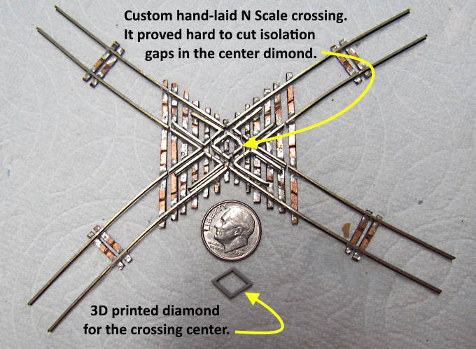
Last year I built the crossing shown below. It fit a non-typical location on the layout that in the end I decide to not do. I found making the crossing off a paper template a lot harder than the turnouts I'd made to that point. One area of difficulty was putting in the insulation gaps in the rails, especially the diamond guard rail section at the center of the crossing. The problem is that the diamond is soldered to only 3 PCB ties there and when you try and cut gaps in the guard rails you end up with small pieces of the diamond attached to only one tie.
This becomes less of a problem for low angle crossings, such as 40 degrees or less and becomes more of a problem with higher angles. This seems to be especially true from what I can find for the smaller N scale crossing. Fast Tracks has printable templates and fixtures for up to 90 degrees for HO crossings but only up to 45 degrees for printable templates and 60 degrees for fixtures in N scale. Not sure if the difficulty is in the gaps or building the crossings. They do have a note about the N scale crossings being in their 'Craftsman Series' which denotes they are more challenging to build. The HO crossings don't have that designation.
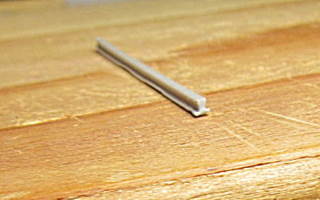
If the diamond guard rails were made from something non-conductive and glued to the ties the problem of having to cut isolation gaps would go away. My thought was maybe design and print a non-conductive 3D printed diamond. I started by designing a single rail...
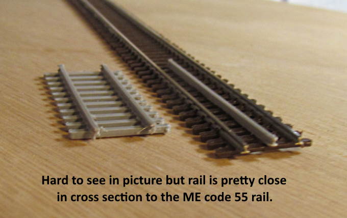
… with Fusion 360 and printing it with my Ender 3 Pro filament printer to see how it would come out. I got the cross-section relatively close to a ME rail. Next I designed …
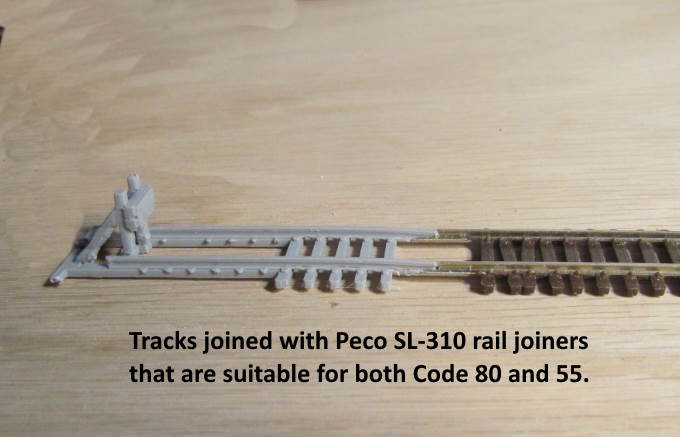
… a piece of track to see how it would look and ….
… ended up designing an 'end of track' section ( more info and files for it HERE ).
I was happy with the results of the above so ….
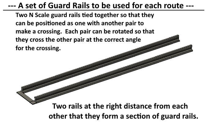
…. designed a section of two guard rails with a connecting piece between them on one end. I made the above a 'component' in Fusion 360. That allows me to copy and paste it into a new design. Then when I move or rotate it both rails will move and rotate and stay the proper distance apart.
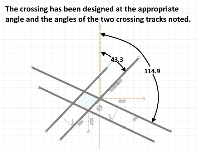
With that done in Fusion 360 I used the 'Insert' command to place the drawing I had made with Sketchup Make on the X-Y plane. I had made this drawing when I built the crossing. With it positioned on the X-Y plane I could measure the angles with the 'Line' command as shown above.
Next I started a new design and ….
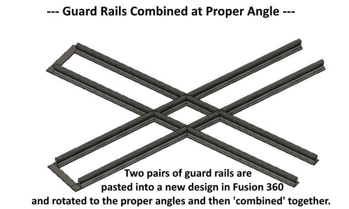
…. pasted one set of the guard rails I'd made onto the X-Y plane. I rotated it to match one set of tracks (43.3 degrees). Then I pasted a second set of guard rails onto the X-Y plane and rotated it to match the other set of tracks (114.9 degrees). The result is shown above. I used the 'Combine' command to make them one body/component.
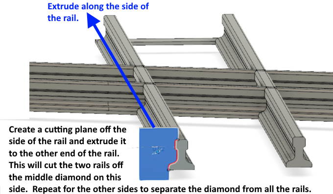
I now had the diamond center but needed to remove the tracks that ran off of it. This is easy to do with Fusion 360. I selected the plane that was the end of one of the rails. Next I drew series of connecting lines off the top of the rail, down one side, over and back and up to the rail on the bottom. That created the 'profile/planar face' (blue area above) to the side of the rail with one side of it the shape of the outline of the side of the rail (red line).
I used the 'Extrude' command and extruded the 'profile/planar face' down the length of the rail. That cut a path through the two rails attached to the center diamond on that side of the diamond.
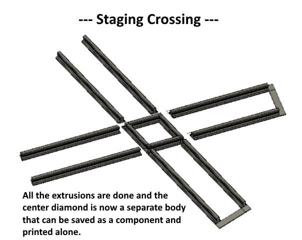
I continued the same process, as shown above, to free the diamond from the other rails ending up with the diamond free of the rails. This is quicker and easier to do with Fusion 360 than trying to explain how to do it.
With the diamond separate from the rails you can make it a new separate 'component' and save it and print it.
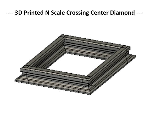
It prints as a single piece as shown above.
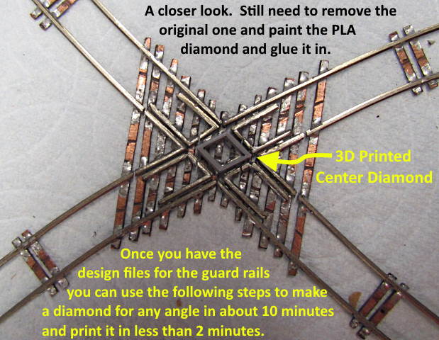
It seems to be as good as or better than the one I had soldered up from ME Code 55 rail.
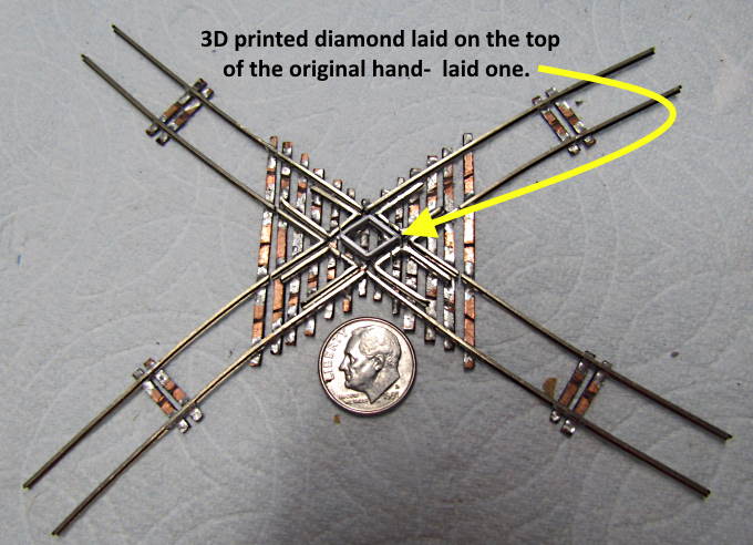
Above it is laying on the the diamond that is still attached to the crossing. I need to unsolder it. Paint the 3D printed one, add wood ties to the crossing and paint all of it. I'll try and update this when I do.
I've added the files to my thingiverse.com account ( HERE ) for the two guard rails that are attached to each other. It won't do anyone much good unless they can use Fusion 360 to make the diamond as I outlined above. The other option is to find a friend that could do it. Also this won't apply to anyone other than someone hand laying crossings that feels this has merit. This probably leaves only me using it but that is OK.
One can print the rails and use them for possibly another project. If you have questions on the procedure above contact me at contact20 (at) purplesagetradingpost (dot) com.
On the next page you will find 3D printed crossing center diamond print files for 14, 19, 30, 45, 60 and 90 degrees.
You can find all the files to 3D print this object and others on my thingiverse.com account ( HERE ).
=========================================
...........................On..............e.........Next Page If There Is One