.................................. Return to Sumner's Home Page....
Return to N Scale RR Main Menu........ Return Roundhouse Menu
=========================================
..............Previous Page..............................Next Page If There Is One
=========================================
.........................--- Roundhouse Floors ---
I'll try my best to describe what I'm going to try doing with the floors. If it isn't clear send me an e-mail (contact20 (at) purplesagetradingpost (dot) com.
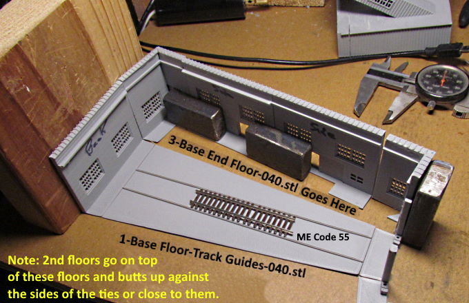
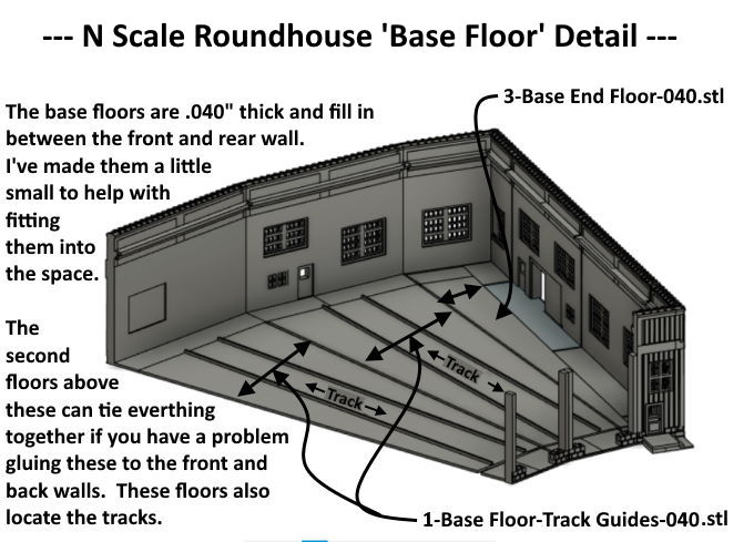
The floors will be in three layers or three floor levels. At the entrance to the roundhouse at the front of the bays there is a base section on the bay fronts. It is .040” thick. There are also .040” thick bases on all the walls to help in the printing as the walls were warping without them. Let's call all of those the base floor. For the track to be level inside the roundhouse we need base floors .040” thick to go from the front walls back to the back wall and also over to the side walls.
I have files that let you print these base sections of floor. The prints are a little small in all directions to make it easier to assemble the model. The two floor layers above the base will let you tie all the floor levels together to the side, front and back walls if you are having a hard time attaching the base floor sections to the walls.
Also you don't need to print all of the base sections out. I've printed a couple but it is a waste of printer time and materials in my mind. I'll use those as patterns and cut the rest out of .040” sheet styrene. Also at that point you could use the patterns on paper and layout the complete base floor as a single floor and use the paper pattern on the styrene to cut out a single larger floor. I'll attempt that my self when I get to that stage of putting everything together. Right now I'm printing the different parts of the building.
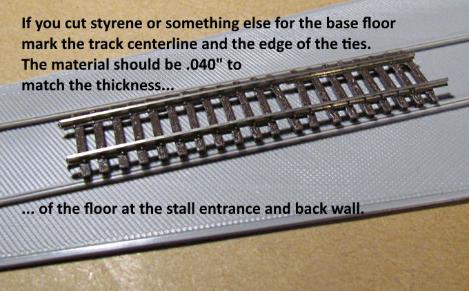
Also on the base prints for the stalls there are straight long raised sections that make it easy to locate the track. If you use the styrene use your patterns to mark the track center lines for the next step.
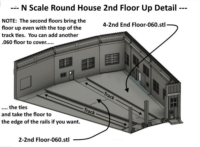
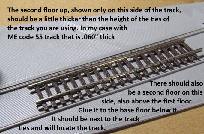
Above the base floor is another floor. It is the thickness of the ME Code 55 track I'm using. The purpose of it is to bring the top of this floor slightly higher than the tops of the ME Code 55 ties. In my case it is .060”. If you are using different track and want to put these additional floors in so that you end up with a shop floor where the top of it is even with the top of the track rails as I believe is the case in real life make this floor out the a thickness that is slightly more than the height of your track ties.
This floor should cover the base sections and extend past it onto the bases of the four walls and close to those walls. It doesn't have to go all the way to them unless this is your final floor. It should go almost to the wall but more importantly close to the edge of the track ties. If you used styrene for the base and have the track centerlines marked put the track in place and butt these pieces up close to the ties. They will now locate the track from moving sideways. Again this will be covered in the next step so some gaps are OK. Also if you weren't able to glue the base floor into position now you can glue it to these pieces and these pieces to the base of the walls tying it all together.
The final step and it isn't shown here is explained further below.
.
Another overview starting with the photo above. Base .040” floor shown with the track inside the locator strips. If you use styrene mark the centerlines.
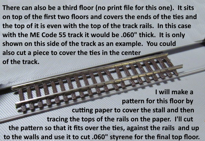
In the picture above only pay attention to the side above the track. I laid a piece that is .060” for illustration above. If you have the piece with the raise track locators butt it up against those. If not butt it up close to the ties once the track is on the centerline. Do this with pieces on both sides that are a little thick than your ties for the track you are using. These pieces will hold the next pieces a little higher than the ties.
Above I've laid the third floor (.060” in my case) on top of the second floor. The top of this floor is even with or close to the height of the top of the rails like it would be in a real building. Since the second piece is a little higher than the ties you should be able to slide the track in and out if you need to.
Try and take this final floor not only to the rail edges but to the wall edges before it is glued into place for a finished floor look. You could also use strips of the same material between the rails or cut some of those ties out and have a work pit between the rails.
There are no printable patterns for this final floor as it needs to be as tight a fit as possible. Use multiple pieces of paper if needed along the rails and the edges of the walls to get a good fit. Tape them together and to a center section of paper and use all of that to make a final pattern on paper or poster-board or card-stock. The use the final pattern to cut the floor out of .060” styrene or the thickness you need for your track.
Take pictures and send them to me and I'll post some. I'll also come back and post pictures here when I get to this stage.
You can find the print files for these floor sections that you can use to make the floor or for patterns ( HERE ).
=========================================
You can find all the files to 3D print this object and others on my thingiverse.com account ( HERE ).
=========================================
...........................On..............e.........Next Page If There Is One