.................................. Return to Sumner's Home Page....
Return to N Scale RR Main Menu........ Return to Decoder Install Menu
=========================================
...............Previous Page.............................Next Page If There Is One
=========================================
--- ESU LokSound for Atlas N Scale '95-'96 GP7/9's – Pt. 3---
============================================
Finishing up the LokSound install in the two Atlas GP7's.
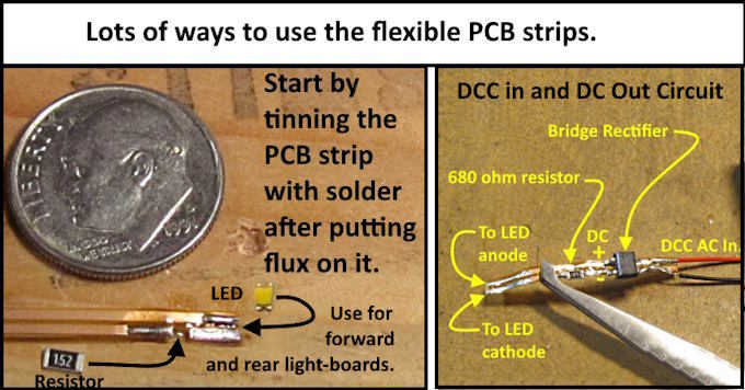
Above and below I'll show some of the ways I use small flat flexible printed circuit board (PCB) strips. These are hard to find in the states but fairly easy to find in Europe. I first saw them used by SteamPower4Ever on nscale.net. He also helped me in getting some but later was able to order some out of England. There is a ton of ways you can use these in projects so would recommend getting some if you can. I have more info on using them and where you might find them ( HERE ).
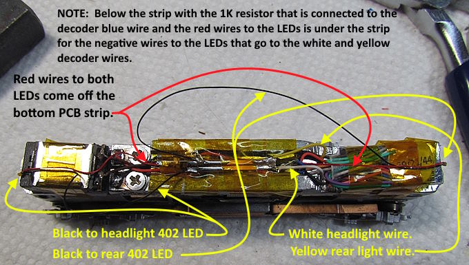
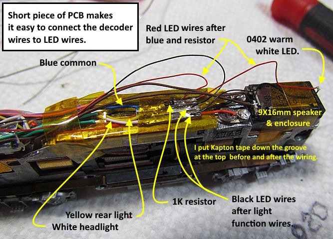
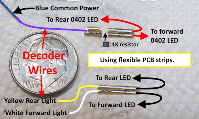
In this build I'm using one short strip to connect the blue common wire to a 1K resistor and on to the anode wires going to the forward and rear LEDs (top above). Using another short strip to connect the white and yellow decoder function wires to the cathode wires for those LEDs. In the images below the strip for the white and yellow decoder wires lays on top of the other strip making it hard to see the strip with the resistor in the images.
The strips are thin and also the wires to the 0402 LEDs are only about .012”/.3mm thick so are not usually a problem fitting under even a shell with hardly any clearance. The same with the 0402 LEDs. Above they are the very small bumps at the end of the wires but have plenty of light intensity. I generally use a 1K resistor but you might like a different value. The ESU decoder also allows some adjustment of the light intensity which is nice.
On some installs I've put the resistor on a strip and the LED on the front of it (bridges from one side to the other). Then run the strip from one end of the loco to where the decoder is and solder the decoder wires to it there. On the right above I made a circuit for one of the lights on my turntable. It takes the DCC AC voltage to the turntable and converts it into DC using a very small bridge rectifier. When the track power to the turntable is toggled on then a white light in the arch over the turntable bridge comes on with no additional wiring to the light needed. More on the turntable and the wiring ( HERE ). I have the 3D print file links there also. They have become a popular download.
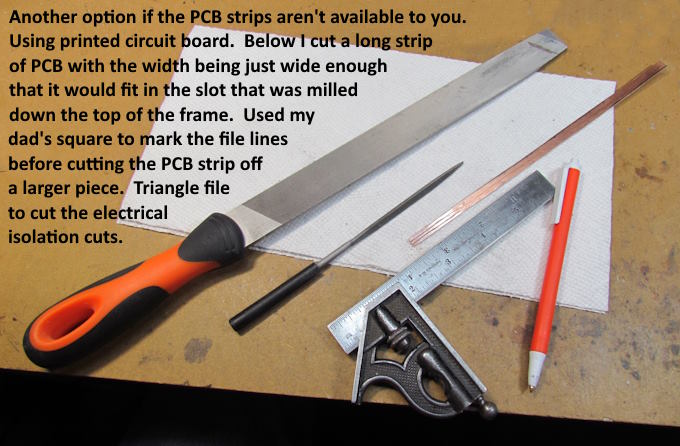
I thought I'd show an alternate solution if you don't have access to the PCB strips or don't want to use them. I use solder pads of different types all over the layout and for other projects. Like them usually over terminal strips. They take up less room and it is easy to solder wires on or off them quickly and they are very inexpensive to use. You can buy and have a lot of printed circuit board bought and delivered for less than $10 that you can cut easily with hand shears for use.
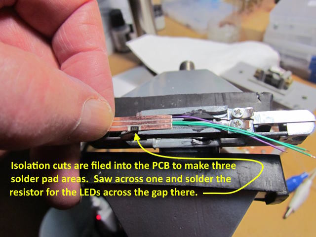
Above I cut the long strip shown that will fit into the channel that was milled into the top of the two frame halves. I then took the triangle file and started making parallel cuts into the PCB. Once far enough for the piece I need I can cut it off and then continue on for other pieces if they are the same. If the triangle file is good this is really fast as the copper is not very thick.
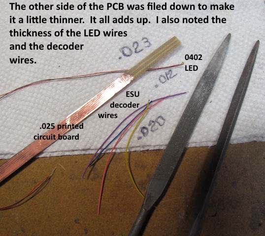
To thin the PCB up a little more and to get rid of the conductive surface on the bottom as I don't need it here I filed the copper off that side and some of the fiberglass under it. Once could also use this side if they needed it for more wiring running in the same direction.
Next not shown I took a jewelry's saw and cut through one of the outer conductive strips to make a gap for the resistor. Make sure you check with a VOM that you did a good job with the file and none of the three strips are conducting to the one next to it. I then soldered the 1K resistor to that conductor with the gap under it.
Above one can see how the PCB is handling the wiring for the decoder wires to the front and rear LEDs and the common blue and resistor all in a fairly small package and it is easy to solder the wires to it. Tin the strip, solder the resistor on, tin the wires and finally with a hot iron and just a touch of solder you can solder any of the components to the strip. Hold the component in place and just touch the iron on and off and you will have a good solder joint. You want the iron hot so that it happens almost instantaneously. I run my iron as hot as it goes. You don't need to spend a ton on soldering equipment. I use a $15 dollar iron for every thing I do. More on it and flux, solder and other soldering tips ( HERE ).
Above you can also see the two brown decoder wires that go to the speaker at the front of the loco. Tin the contacts on the speaker and the wires and solder them like was mentioned above. I have the print files for this speaker enclosure and some other ones ( HERE ).
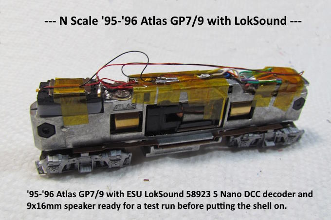
Time to get the loco on the test track and see how things work.
Click the image above or ( HERE ) for the running of the first of the two installs.
Click the image above or ( HERE ) to view the two sound GP7's running together (which they won't be on the layout as they will both have their own train, one loaded and one empty).
Thanks to woodone for his input when I was wondering about a few things at the beginning of the build and pictures of his build showing the speaker location and how to connect to the frame halves for track power pickup.
Next hopefully is 4 LokPilot installs in the other 4 GP7's that will be used in the two coal trains.
=========================================
...........................On..............e.........Next Page If There Is One