.................................. Return to Sumner's Home Page....
Return to N Scale RR Main Menu........ Return to Decoder Install Menu
=========================================
...............Previous Page.............................Next Page If There Is One
=========================================
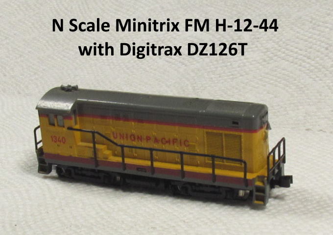
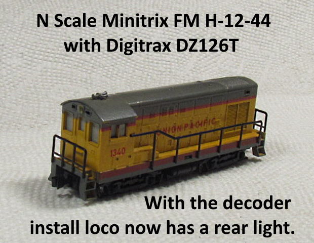
........--- Minitrix FM H-12-44 Decoder Part 3 ---
=========================================
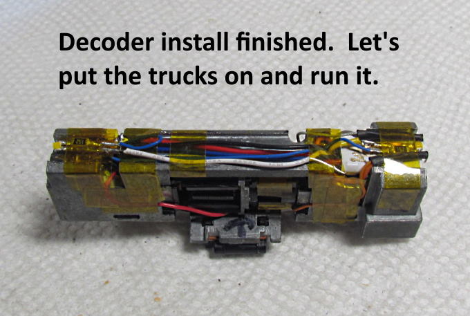
First thing is to finish up the rear LED light.
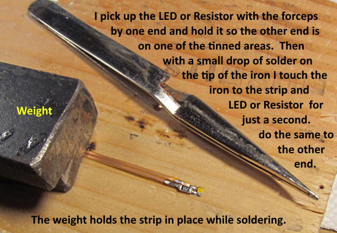
Soldering the small LED and resistor can be intimidating. The flex PCB helps with this as it lays flat. I put a weight on it and leave the strip long at this point as it is easier to hold. With the strip pre-tinned you can pick up the LED or resistor and hold it by one end and place it on top of the tinned section. Put a very small drop of solder on the end of your iron (first) and then just touch the iron to the LED/Resistor and the strip at the same time and remove it quickly as soon as you see the solder flow onto the LED/Resistor. With one end soldered on move to the other end and solder it. It will be easier as it is in place held by the other end.
With the components soldered on I test across the resistor with an ohm meter to make sure it is soldered to both sides. I also use a LED tester I have to test across the LED to make sure it is working. Remember that the LED is polarity sensitive so you need positive going to the anode side and negative to the cathode side. If it doesn't light swap the leads and see if it does. You can check the whole assembly by running the current through both the resistor and LED.
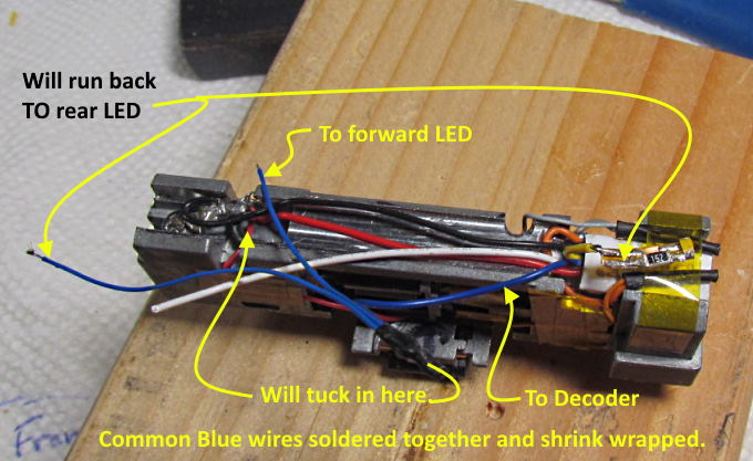
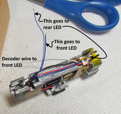
I think if I was to run the common blue wires again I would of gone from the decoder with a very short wire to a short strip of the flexible PCB and off of it to the front and rear LED's. The above did work as there was the former light pocket at the front where I could tuck the connection of the three wires into.
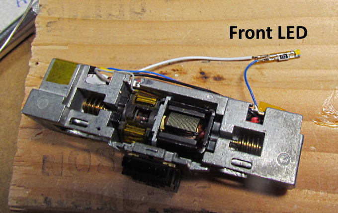
Above one can see where the connection of the three wires got placed.
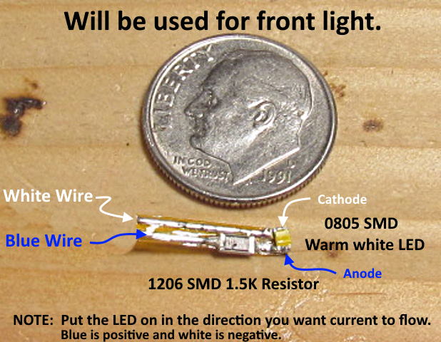
As mentioned earlier the LED is polarity sensitive so you should look at the markings on it and place it in the short circuit in a way that suits you. However if you mistakenly soldered it into the circuit backwards that is no problem. Just swap the blue wire and the other decoder wire (white or yellow) around and the LED should work fine. It doesn't matter if the current flows through the resistor before or after the LED.
.
.
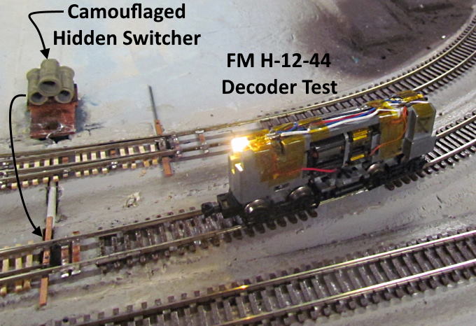
One thing I'm using the test track for is to also test out some of my different turnout controls. I'm using three of the 'Hidden Switchers' (one shown above) and four of my 'Gravity Switches' for the turnouts on the test layout. Above moving the stack of 'culverts' back and forth activates the one turnout and also changes the polarity of the frog. More about the Hidden Switcher and the Gravity Switcher ( HERE ).
.
.
Want to see this guy run on the test track? Click ( HERE ) or above.
Overall I'm happy with the decoder install in the FM H-12-44. It doesn't have the really slow speed running capabilities of most of my other older DC loco's I've converted to DCC but it is also a much older design coming out in the '70's vs. the '90's or newer. It does navigate the ME code 55 track and my code 55 hand-laid turnouts for the most part despite having 'cookie cutters' for wheels. I doubt I'll try to turn them down as I probably won't use this loco much since UP didn't have any FM H-12-44's only the H-10-44'S and some other FM locos.
=========================================
...........................On..............e.........Next Page If There Is One