...Return To Mine & Other Bonneville Car Construction Pages
.Previous Page...........B'ville Car Index Page...............Next Page
==================================================================
...--- Remote Throttle Position Sensor Mount (TPS) ---
......................................--- Part I ---
==================================================================
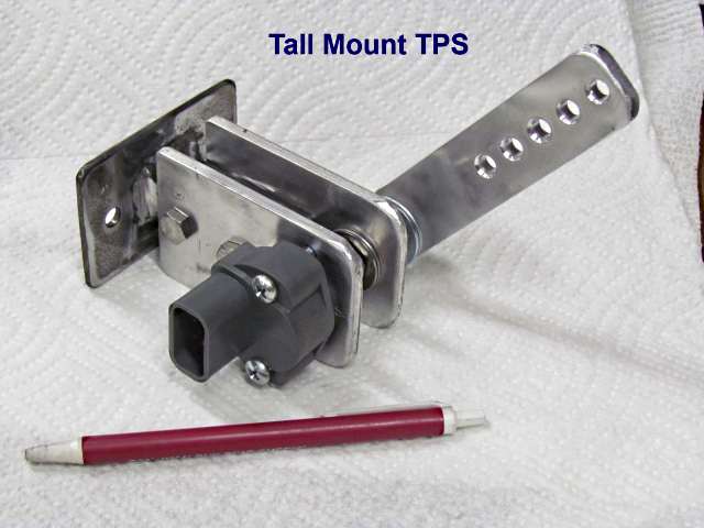
On this page and the next I'll show three remote Throttle Position Mounts I've made. I've also made ones that fitted right onto the bell crank of the carb but found that these are more adaptable to different carb linkages and mounting problems. They also use about the cheapest TPS I've been able to find. One found in 90's Dodge pickups. You can find them in the high $20 to $30 range and probably less at the salvage yard. The salt is hard on these so we keep a spare with us on the salt.
I call the one above the "Tall Mount" since the TPS and arm are further from the mounting bracket.
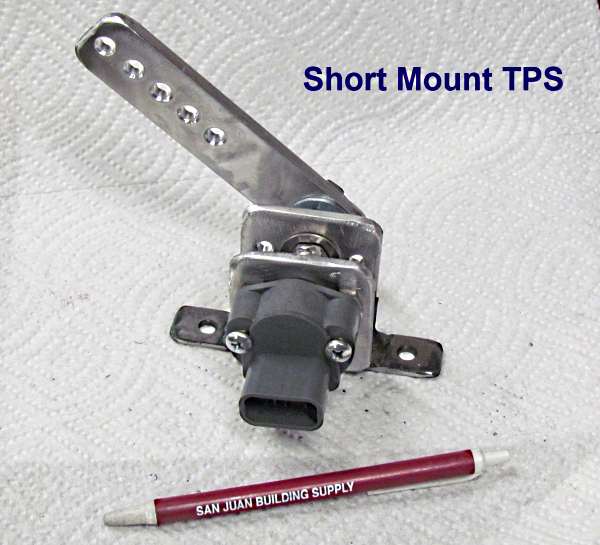
The short mount is more compact but still uses the same Dodge TPS and the arm. The arm can be cut shorter.I
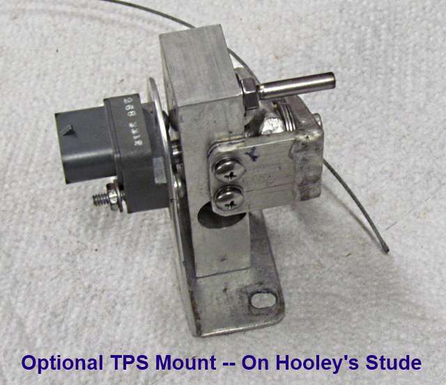
The one above was the first remote mount I made and we use it on Hooley's Studebaker that he runs at Bonneville and 1 mile venues. I'll describe it on this page. One doesn't have to make one like any of these but they should give you an idea to work from.
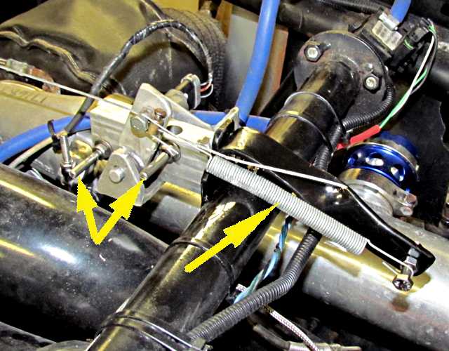
Above you can see the TPS installed, left arrow, the 1/16th cable, center arrow, going to the carb linkage.
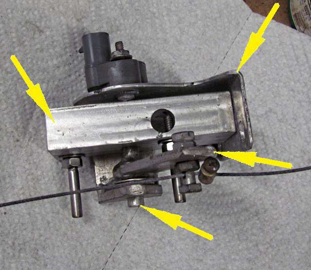
Top right arrow points to the main mounting bracket. The arrow below it to the arm. Bottom arrow points to the shaft that the arm is welded to and the shaft goes through the bearing block, top left arrow, and into the TPS.
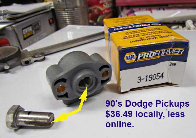
The TPS is for a 90's Dodge pickup and has two ridges in its bore. You can find it at a parts store or at rockauto.com (see search below for the connector). The bolt above has been slotted to fit into the bore and grab the ridges in order to turn the TPS. That bolt is used on the next build page. In this install on the Studebaker the shaft is slotted like the bolt on the TPS end of the shaft.
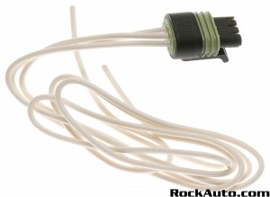
To find an electrical connector go to https://www.rockauto.com/ ...
....and search in the following sequence:
DODGE --- 1996 --- RAM 1500 PICKUP ---5.2L V8 --- Electrical-Connector --- Throttle Position Sensor (TPS) Connector
and you should find it... ( ACDELCO PT2306 {#88862225} Professional ) for under $6.00.
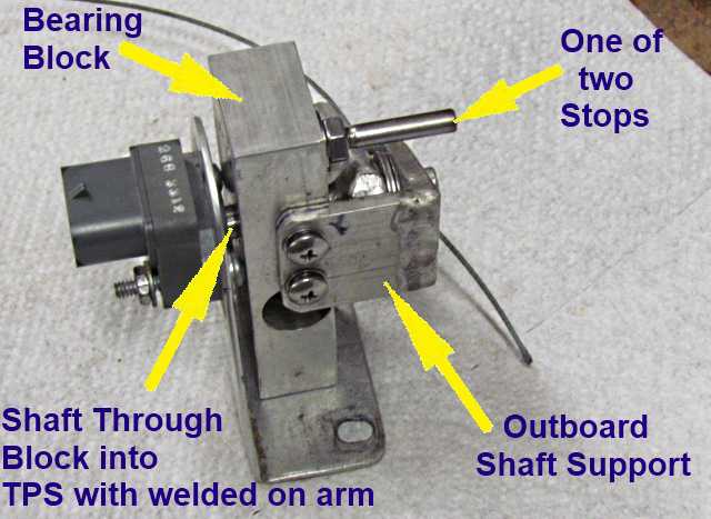
The center bearing block is attached to the bracket with a couple SS screws through the bracket's bottom side and into the block. The block is scrap I had and the hole you see through it above was already in it and serves no purpose.
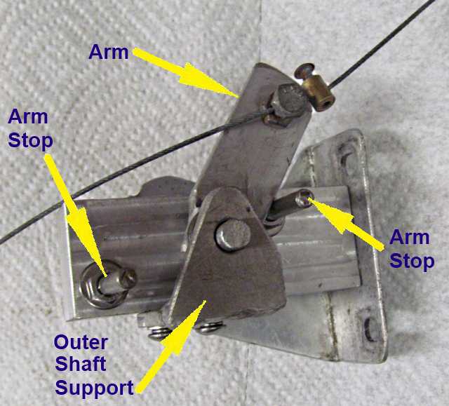
Above you can see the outer support for the shaft that is held to the block with 2 SS screws. The 2 arm stops are just a precaution to avoid turning the TPS too far in either direction as its internal stop is probably not very strong.
Once you have the cable attached to the carb linkage the stops don't come into play as you don't want the carb to pull the arm to the stop as that would also limit the travel of the carb linkage. If you are careful in setting things up you don't need these stops. Just attach to the arm at a distance that keeps the TPS shaft rotation in the range the TPS is designed for. You don't need to have full range as your data logging software will allow you to set zero percent throttle and WOT.
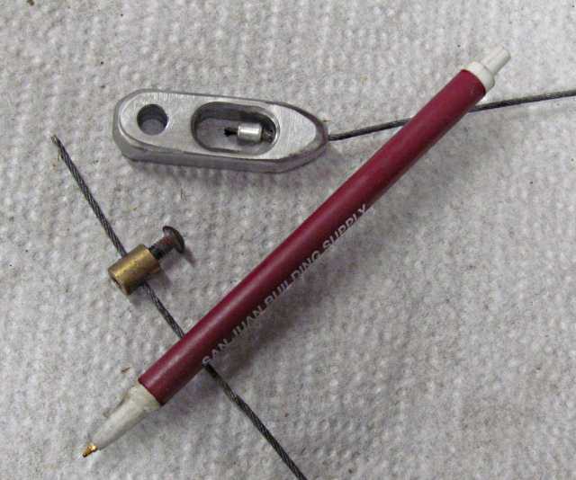
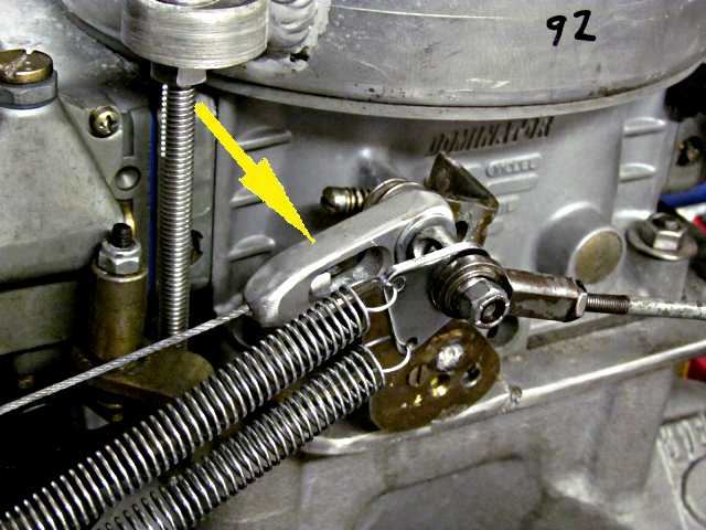
I made the piece above to fit on the throttle linkage shaft where the throttle rod connects out of a piece of aluminum. Slotted the center and drilled the end so that the 1/16th inch cable would go through it and crimped a stop on the cable on the one end and the barrel stop is on the TPS end.
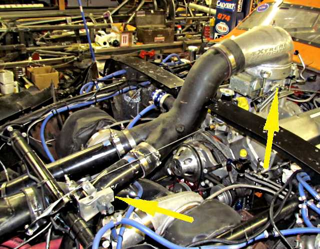
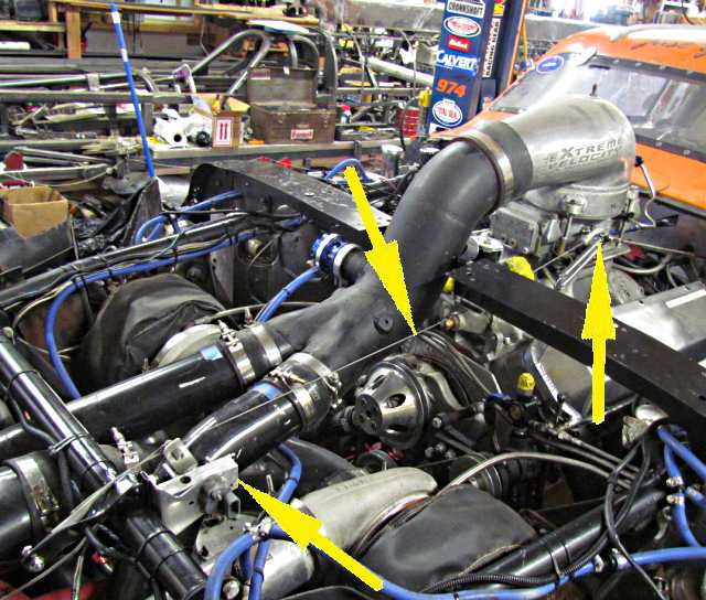
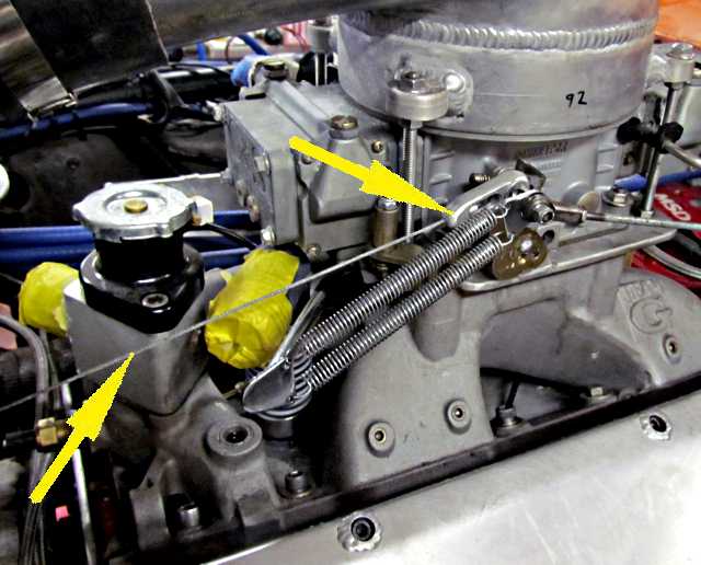
Above you can see the cable running from the TPS mount to the carb. If you can't get the TPS in line with the carb linkage put a small pulley on the cable run at some point and run off in any direction you want. There could even be more than one pulley. We started with a pulley to get the cable under that cross bodywork support under the right arrow and it worked fine with the return spring down on the TPS arm keeping tension on the cable.
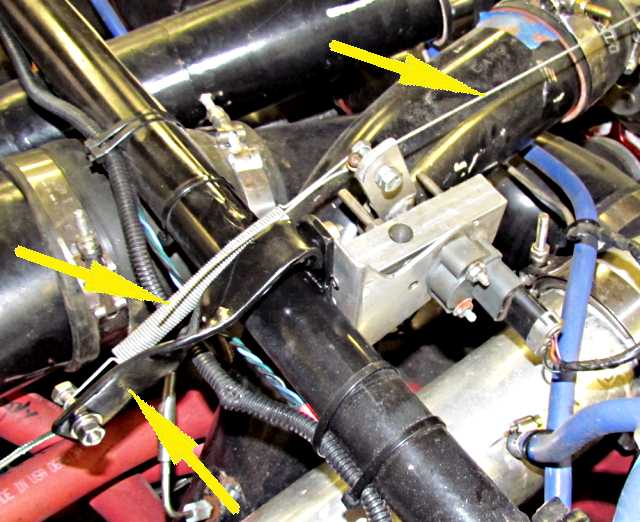
There is a spring bracket used by the TPS that the spring connects to, left arrows. The spring keeps tension on the arm and keeps the cable taught going to the carb, right arrow. This does not have to be a heavy spring as the carb linkage has its own springs.
A view of the other side. Note that the arm is not back on the back stop once everything is mounted and connected. At WOT the arm doesn't touch the front stop either. Again they are just a precaution to protect the TPS's internals before the cable has been connected to the carb linkage and a check that the arm length is correct and not trying to make the TPS rotate more than it was designed for. You can feel the internal stops on the TPS.
The cable going to the carb linkage and ....
.... the piece I made that goes on the linkage.
To test the TPS to make sure it is working I have two leads, red/black, that have straight connectors crimped onto one end. I slightly crip the end that will go on the TPS male prongs. Just enough to hold them on. I connect the other ends of the leads to the ohm meter. Put one lead on the center prong and the other on either end prong. As the TPS's center is rotated you should see a change in the ohm reading.
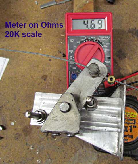
Above with the TPS rotated on way I see 4.69 on the 20K scale with the meter set to read ohms.
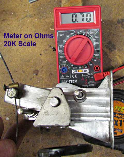
With the arm the other way I see .7. Your numbers might not be exactly the same.
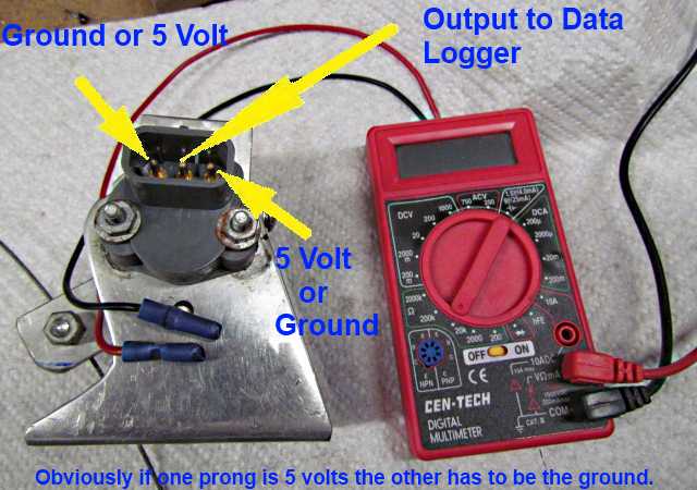
When you wire the TPS you wire the output to your data logger to the center prong. The ground in the stock configuration would be to the left prong above with 5 volts from your data logger going to the right prong.
If your data logger is reading the TPS backwards, WOT when you aren't pushing on the throttle you usally have two options. With Innovate you can just tell the software to read the TPS so that 0 volts is WOT and up to 5 volts is 'no throttle'. You could also swap the ground and 5 volt leads to the TPS and do the same thing. Just make sure your output is the center prong.
Also the software should allow you to pick any voltage as no throttle and any other voltage as WOT. For instance 1.3 volts might be 'no throttle' and 4.2 volts might be WOT. Consult your data logger instructions.
On the next page are two more mounting options but other than that everything else above applies to them also,
Sumner
==================================================================
Next Page... Next Page