.................................. Return to Sumner's Home Page....
Return to N Scale RR Main Menu.............. Return to Locomotive Menu
=========================================
..............Previous Page..............................Next Page If There Is One
=========================================
.NOTE: If anyone takes the time to print these gears I would sure like some feedback that would mainly help others. Let me know the printer and resin you used and the results. I've only used the Siraya Tech 'Build Sonic Grey'. Good results so far on detail and durability but my testing hasn't been extensive. There are a ton of resins out there so I'd like to know what has actually worked ( contactsumner1 (at) gmail (dot) com ).
=========================================
…..--- 3D Printed Gears for Bachmann DDA40X ---
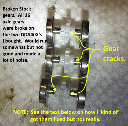
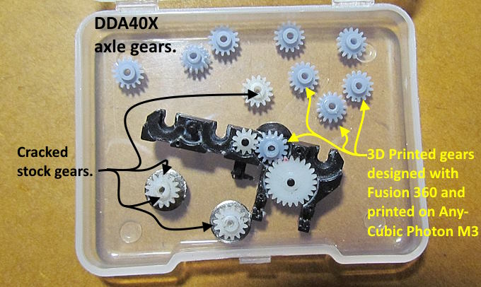
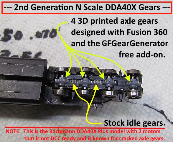
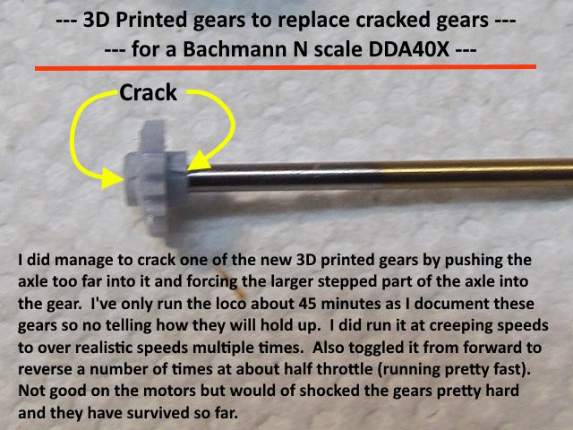
I have a few of the Bachmann 2nd generation DDA40X locomotives. I saw them when they were new and I lived in Laramie, Wyoming so they are kind of special to me. The Bachmann's have dual motors like the originals and also most have a common fairly fatal flaw. The have the notorious Bachmann 'White Axle Gears' that split like in the first image below. Bachmann no longer has replacement gears and as far as I can tell no one else has them either. James at James Trains has replacements for the Bachmann Doodlebug and might make them for the DDA40X's at some point also but as I write this (Aug 2023) doesn't as far as I know.
For some time I had thought about trying to design gears and 3D print them but thought designing gears had a 'black magic' like aspect to it. Recently searching about this I found that the free Fusion 360 I use has an also free add-on called GFGearGenerator that makes designing gears super easy. You do need to have some knowledge about gears to use it though.
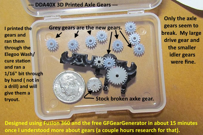
I spent a couple hours searching and reading and view what I needed to use the program and in about 30 minutes with Fusion 360 I had an axle gear that I could print on an AnyCubic Photo M3 resin printer. 50 minutes of print time and a few minutes of cleanup and I had a number of gears to try out. The following takes it from there and if you find Part 1 to boring skip to Part 2.
===== Part 1 – What you need to design a gear =====
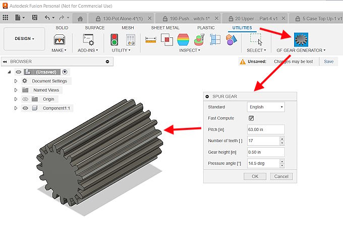
After you add GFGearGenerator to Fusion 360 ( Download Here ) you need a couple things to use it to design a gear, but not much and it will do the rest. You need to know the 'Standard' (metric/English); the 'Module' (metric) or 'Pitch- (English); 'Number of teeth'; 'Gear Height' (thickness) and the 'Pressure Angle'.
I knew the number of teeth from the stock gear. I knew the thickness of the gear from measuring the stock gear. I'd try a 14.5 pressure angle as that seems to be the common angle widely used. The only real unknown was what module or pitch do I use. The YouTube video ( HERE ) gave me the answer pretty quickly.
To determine the 'Pitch' you only need the number of teeth and the overall diameter of the gear in inches and the formula [ Pitch = (2 + # teeth)/ O.D. in inches ]. If you use Module you also only need the number of teeth and the overall diameter of the gear in mm). Pretty simple and explained in that video. I had the three stock gears (drive, idle & axle) that I knew the number of teeth on and could get close on the diameter of the gear. Using that and the video info I came up with a pitch of 63 on one gear, 65 on another and 64 on the third. All of the gears that mesh together, the larger drive gear in the gear tower and the axle gears and the idle gears have to be and are the same pitch. The small differences in the pitch numbers was due to accuracy in measuring the diameter to a thousands of an inch. Since 64 was a very common pitch I went with that and it seems to be right.
Using a pitch of 64 as the 'Pitch' in Fusion 360 I had a gear that ended up working first time in under 30 minutes. So much for 'Black Magic' although it still would be that without the GFGearGenerator add-on as it did all the heavy lifting.
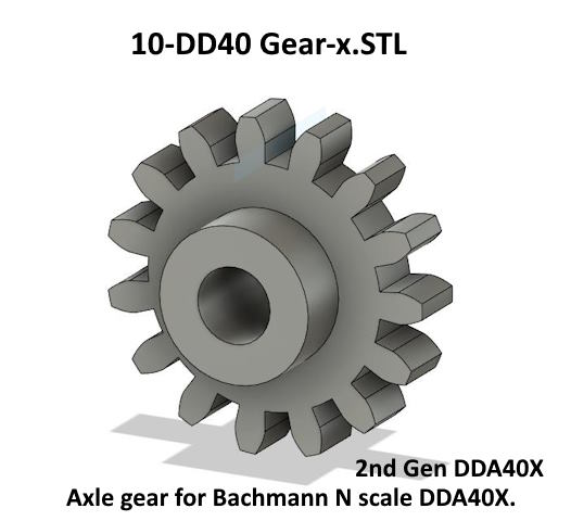
With the basic gear designed by GFGearGenerator I only had to put the inner bore in the gear and the shoulders on both sides of the gear with Fusion 360, simple an quick to do.
The gears were the first print I did with the AnyCubic Photon M3 and they came out great. The secret to that was I used the Siraya Tech's print profile for the M3 using their 'Build Sonic Grey' resin (love this resin so far). You can get the print profiles on Siraya Tech's site and add them to Chitubox which is the slicer I used. I chose light supports using it and the print was great right off the build plate. The gears snapped off the supports after I washed them on the build plate in the Elegoo 'Wash-n-Cure' station. After they were washed I put the gears alone back in the cure option of the station and cured them for about 2-3 minutes on each side. Next in part 2 the gears will be installed.
====== Part 2 – Installing & Testing the gears ======
The following will explain installing and testing the gears in the loco.
.
I did get the loco running pretty will with one of the two trucks but not like you would want it as the gears in one truck would bind up and stop the loco at time. Not good on the motors.
I couldn't believe how well the gears printed and what little cleanup was needed after coming off the build plate and the wash and cure session which is very easy using the Elegoo 'wash-n-cure' station. No hand cleaning required with it.
Less than 30 minutes to design the gears in Fusion 360 once I spent a couple hours learning more about gears.
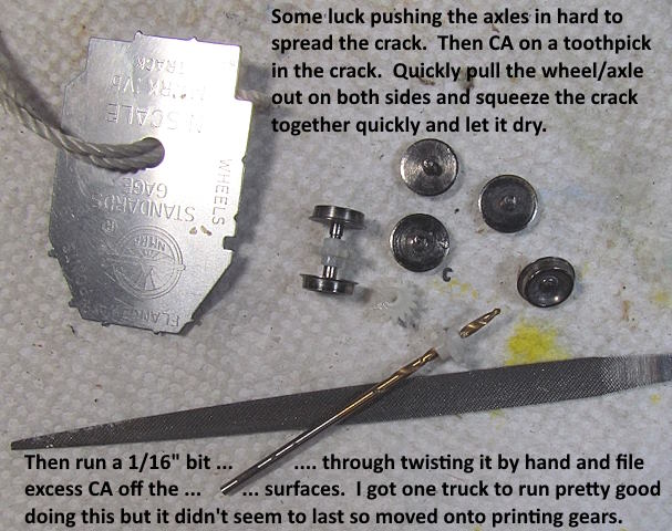
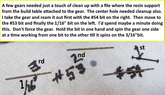
It is very important to bore the center of the gear out and doesn't take long using the three bits shown above. You want to end up with it spinning freely on the 3rd bit ( 1/16”). Don't overdo it though. You want the two axle half's to be a slight press-fit into the gear. If you don't clean the hole up the axle will probably crack/split the gear if it has to be forced in. After a couple you will get the feel. I wondered if I might have to end up using CA glue but so far that hasn't been necessary.
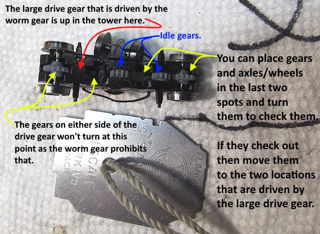
I start by testing the gear/axle combinations in the two bearing locations on the right above. You can put them there and spin the wheel/axles and turn the truck over and push it and see if the bearings and wheels are spinning freely. After you know they are then put two in under the drive gear (the worm gear on top of the large drive gear prevents you from spinning the two axles that are driven by the drive gear. Also once they are in place none of the gears will turn by hand as they are all connected via the idler gears.
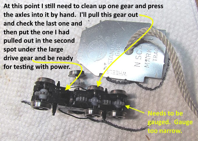
Be sure and gauge the gear/axle combinations as you press the axle/wheels into the gears with a NMRA gauge.
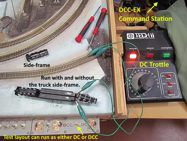
I run the trucks on the workbench with the small 5v power supply on the end of a breadboard or take it over to the test layout and run the motors/trucks with some leads clipped to the track. This is good as you can run them at all speeds with the loco upside down. Clip the leads to each frame half. The gears/wheels might jump around a bit until you put the side truck frames on.
Above is a gear I cracked by pushing too hard on the axle while inserting it into the gear and the larger diameter step was forced into the gear and split it. Only time will tell how the gears stand up to longer run times on the layout. I'd like to hear your results if you print and use them and will pass that info on here. Contact me at ...
contactsumner1 (at) gmail (dot) com
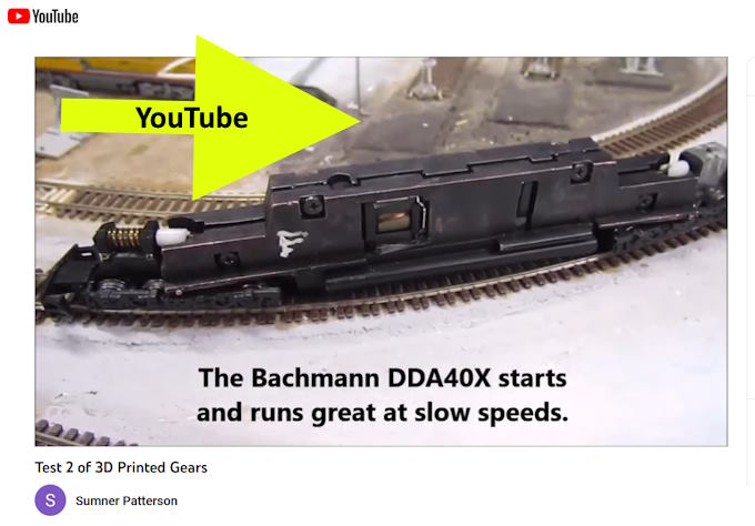
Click on the image above or ( HERE ) to see the gear test on the bench followed by testing on the test track.
I made another batch of gears since I need one for this loco and eight more for the second one that needs new gears.
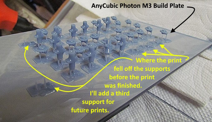
I print a number of extra as it takes the same amount of time no matter how many or on the build plate and some fall off during the print as I selected the smallest support possible. I'll add a third support for the gears on future one and maybe not as many will fall off.
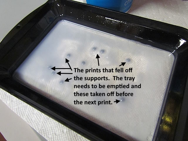
The ones that fall off end up on the bottom of the resin tray. I use HF paint filters (100 for $9) to put the resin from the vat into a cottage cheese container. Scrape the failed prints off above and then use the filter to pour the resin back into the vat.
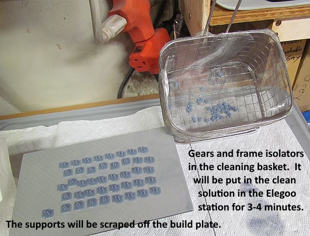
The first couple of runs printing the gears and frame isolators I let the build plate drip back into the vat for quite a while. Then stuck it into the cleaning container that has denatured alcohol in it. The container sits in the Elegoo wash/cure station and propeller in the container spins and washes the print. There was still fair amount of resin on the build plate that was also washed off. Not great as it is wasted and contaminates the denatured alcohol faster.
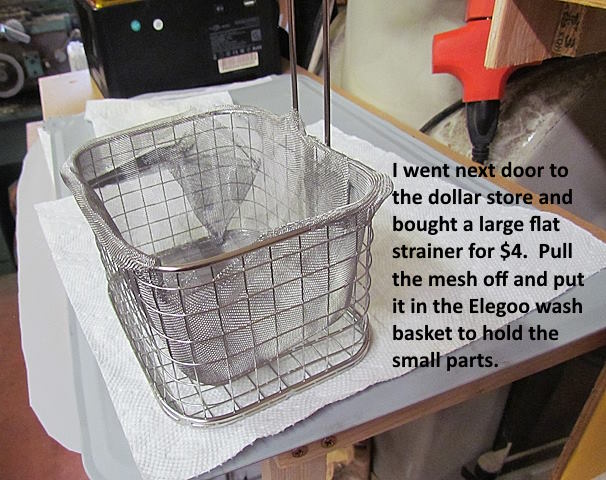
There is a basket you can put in the wash container but these small parts would fall through and down to the propeller. I found a large flat strainer for $4.00 at the Dollar Store next door (handy location for us) and removed the wire netting and pushed it into the basket and ….
…. put the gears and frame isolators into the basket and lowered it into the denatured alcohol and ran the clean cycle on the station for about 4 minutes.
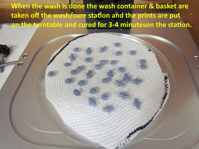
Next the wash container was removed from the station and the round curing disc was put in its place.
I ran the 'cure' cycle' for about 3 minutes. Tried to turn the prints over the best I could and ran it another couple minutes. The wash/cure station is a great addition to the printer and if it went down I'd be ordering another one right away.
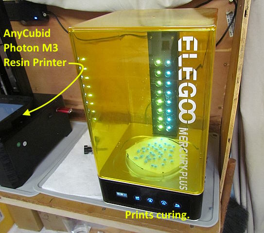
Below the printer and wash/cure station shown above are shelves where all the supplies and eqipment needed for resin printing are stored. There is another shelf to the left out of view that I use for dealing with the build plate when it comes out of the printer and is a place I can pour resin in or out of the vats. To the right in the picture above you can see the edge of a bed sheet that gets pulled over the whole station when not in use to help eliminate dust. I'm glad I took the time to build the print station as it has made the whole process that I wasn't looking forward to very manageable and actually enjoyable.
I printed a lot of gears since they don't use much resin and print as fast as one which was all I needed and I'll need more for the second DDA40X I have that also has cracked gears. I put the one gear in the loco and tested it first with my 5 volt power supply and then moved over to the layout where I could connect it to the track power as shown above. It was catching a little and stalling the motor in one direction so pulled the gears/axles/wheels back out and tested them one at a time in the truck housing and they all seemed fine. Put them all back in and everything ran fine. Not sure what was going on.
After the test with the loco upside down it was onto the test track and the loco as you can see is running great at all speeds (click on image above or HERE ).
I have no long term report at this point as to if the gears will hold up or not but so far I'm impressed and happy with them. Also they cost penny's to make and at this time I've had the loco apart and together and could replace all 8 axle gears and have the loco back on the track in about 30 minutes with new gears if needed.
You can find the print file for the gears on my thingiverse.com account ( HERE ).
=========================================
…..............................................Next Page If There Is One